

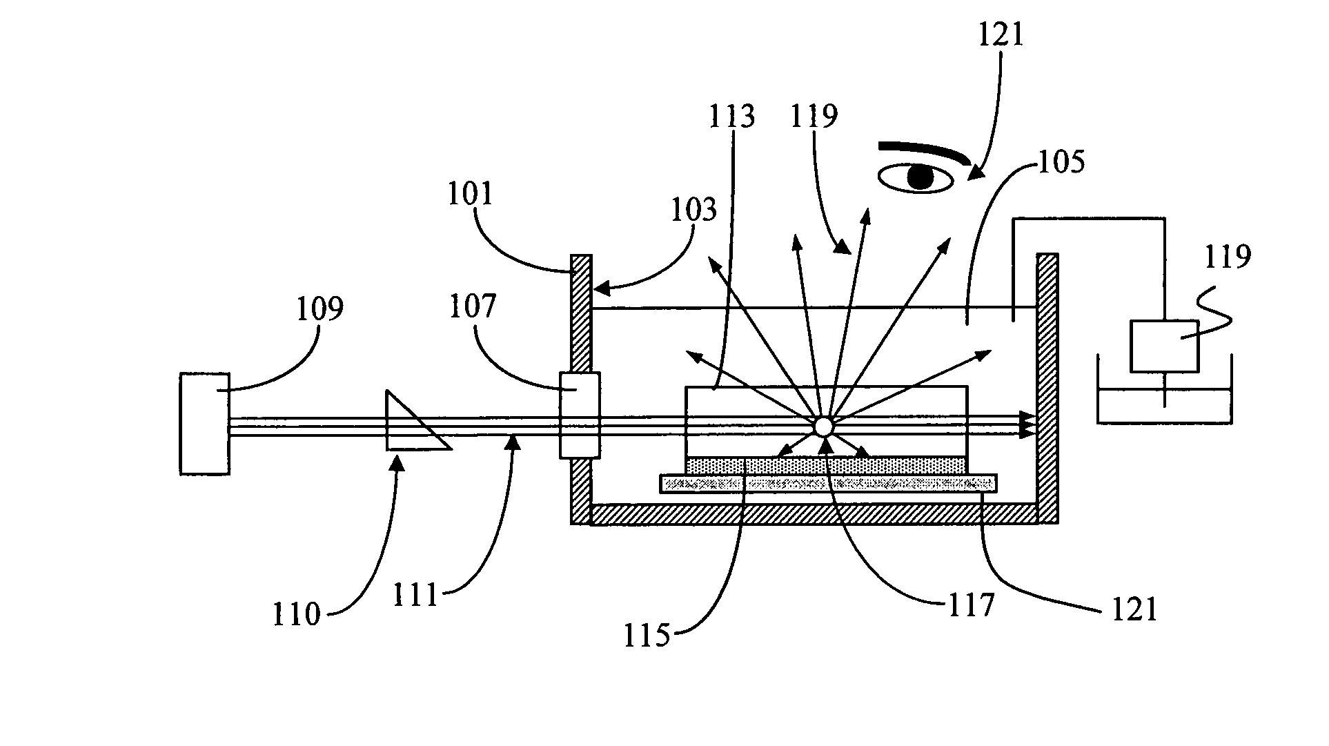
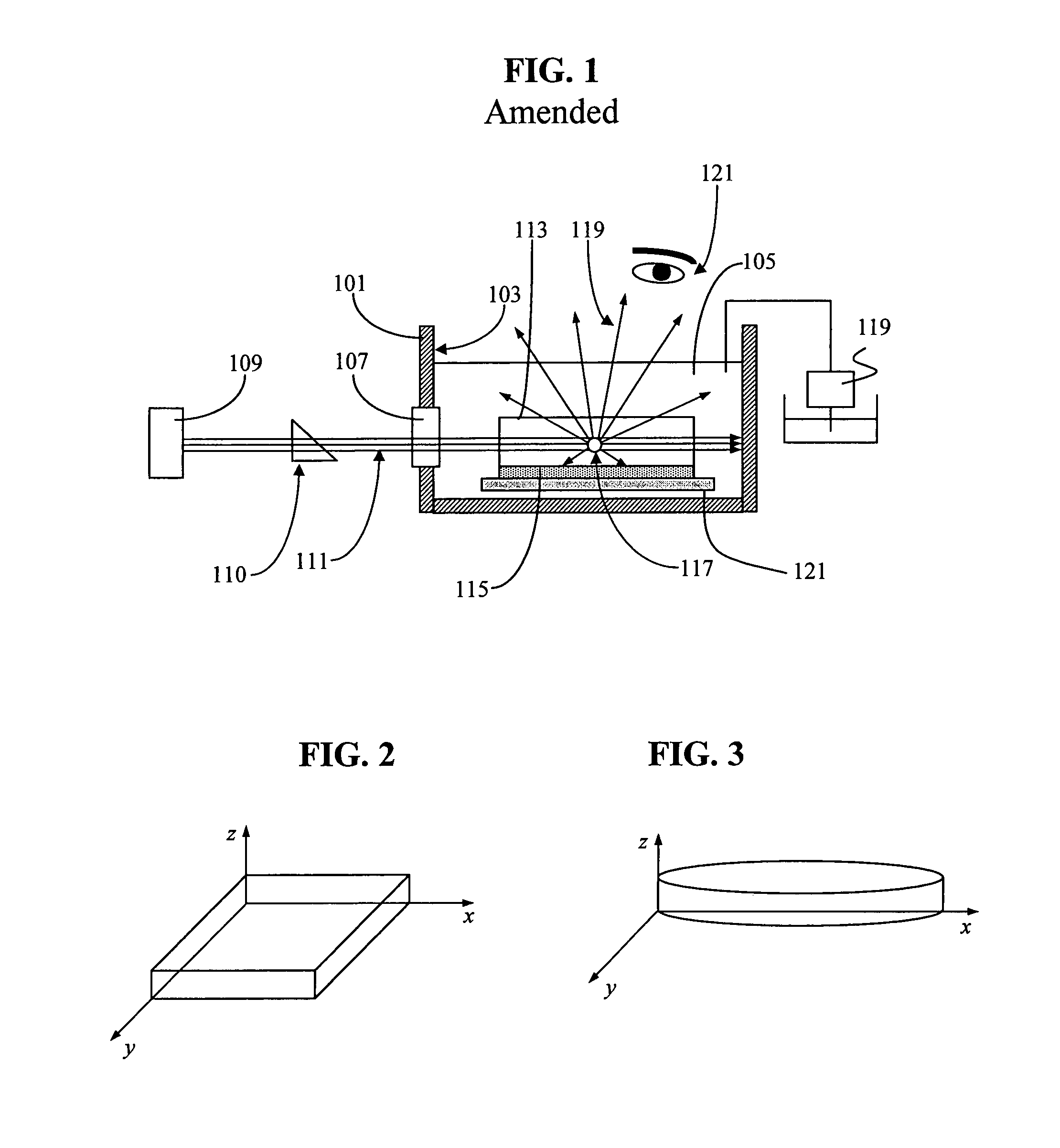
Apparatus and process for detecting inclusions
a technology of inclusions and apparatuses, applied in the field of apparatuses and processes for detecting inclusions, can solve the problems of difficult detection of small inclusions in solid media such as glass, micron size or submicron size, and inability to accept stepper lenses and photomask substrates, and achieve high signal-to-noise ratio, reduce the possibility of human exposure, and high sensitivity for inspection
- Summary
- Abstract
- Description
- Claims
- Application Information
AI Technical Summary
Benefits of technology
Problems solved by technology
Method used
Image

Examples
example 1
[0088]The following composition in TABLE I was prepared by adding the following ingredients into a stainless steel container. The container was placed on a hotplate and the composition was mixed with a stainless steel mixing blade at ˜600 rpm until the mixture reached ˜60° C. The composition was mixed at 600 rpm for one hour at 60° C. After cooling to room temperature the composition was ready for application.
[0089]
TABLE I31.00%Photomer 6891 An aliphatic urethane acrylateoligomer(Cognis Corp. Ambler, PA)25.00%Aronix M111 ethoxylated nonyl phenol acrylate(Toagasei Chemical Industry Co., Tokyo Japan.) 4.00%Irgacure 1800 Photoinitiator blend (Ciba Geigy Corp.,Terrytown, NY)40.00%DSM Cablelite ® 751 Black UV curable optical fiberink (DSM Corp., Des Plaines, IL)
[0090]Photomer 6891 is a viscous and flexible oligomer. Aronix M111 has the following general formula
[0091]
where on average n≈1.4.
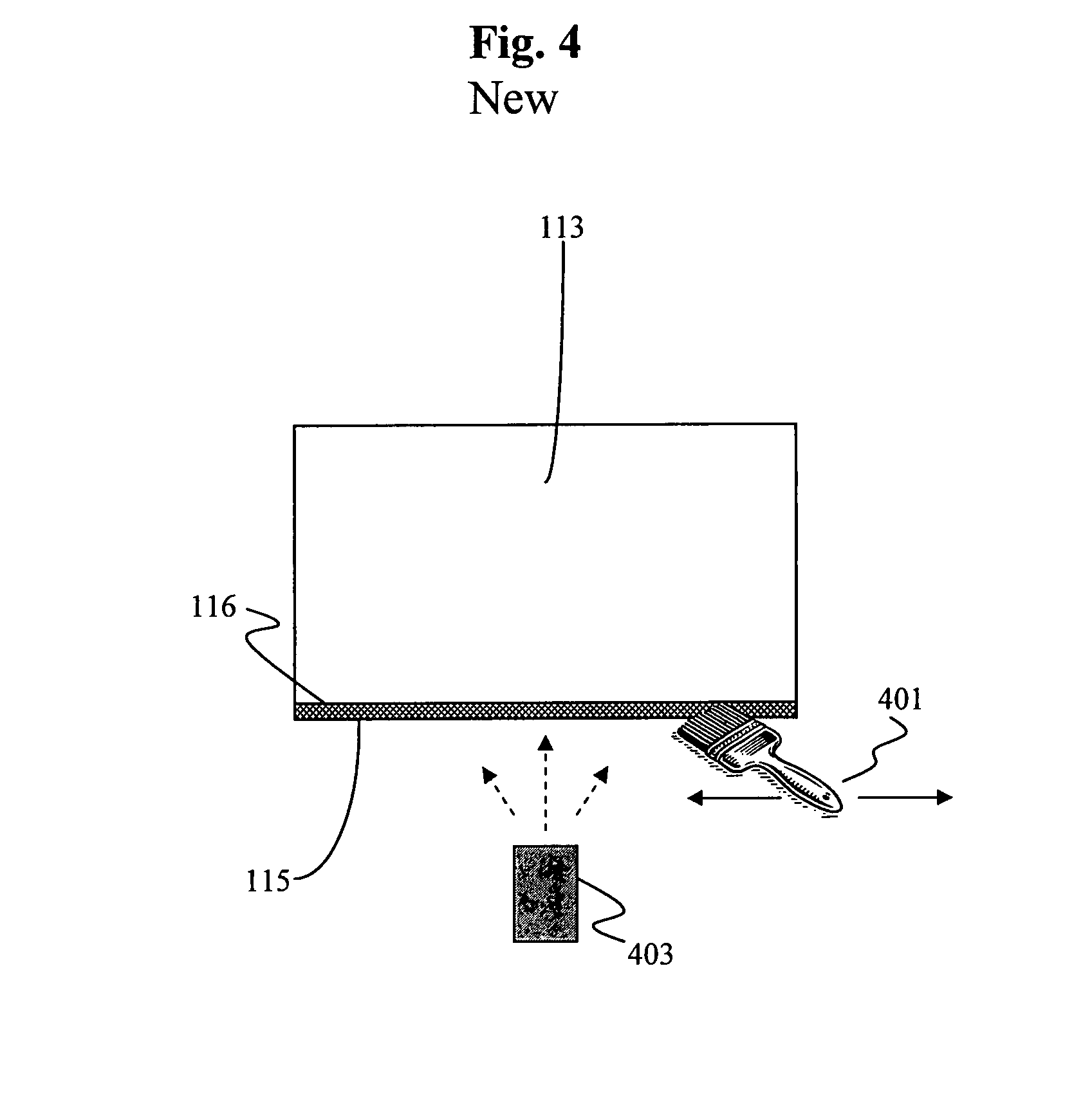
[0092]This composition was applied to a surface of a glass substrate using a paint brush. The black-...
example 2
[0093]The following composition in TABLE II was prepared as in Example 1.
[0094]
TABLE II28.00%Photomer 689122.00%Aronix M-111 6.00%Speedcure EDB (Ethyl-4-(dimethyl amino) benzoatefrom Aceto Corp. Lake Success, NY) 4.00%FirstCure BD-3 (Proprietary maleimide blend fromAlbemarle Corp., Pascagoula, MS)40.00%DSM Cablelite ® 751 Black UV curable optical fiberink (DSM Corp., Des Plaines, IL)
[0095]This composition was drawn down onto a 4″×4″×0.7 mm thick glass plate using a 3 mil Bird applicator. The ˜3 mil thick black film was cured with a Greenspot UV curing unit. The lightguide from the Greenspot UV curing unit was suspended at 2″ above the black film. The UV exposure time was 99.99 sec. The black film cured completely dry to touch and can easily be peeled off of the glass substrate in one piece. The experiment was repeated using a 6 mil Bird applicator to draw down a ˜6 mil black film onto the same size glass plate. The film was UV cured using the same exposure protocol. The film cured c...
PUM
| Property | Measurement | Unit |
|---|---|---|
| surface roughness | aaaaa | aaaaa |
| roughness | aaaaa | aaaaa |
| roughness | aaaaa | aaaaa |
Abstract
Description
Claims
Application Information