
Lithium metal oxide electrodes for lithium batteries

a lithium battery and metal oxide technology, applied in the direction of nickel compounds, manganates/permanentates, cell components, etc., can solve the problems of low lithium content, unstable lithium battery, high cost, etc., and achieve the effect of improving the capacity, cycling efficiency and cycling stability of lithium cells and batteries

Inactive Publication Date: 2008-01-01
UCHICAGO ARGONNE LLC
View PDF6 Cites 92 Cited by
  • Summary
  • Abstract
  • Description
  • Claims
  • Application Information

AI Technical Summary

Benefits of technology

[0007]This invention relates to improved lithium-metal-oxide positive electrodes for lithium cells and batteries, preferably rechargeable lithium-ion cells and batteries. More specifically, it relates to layered lithium-metal-oxide electrodes, represented by the general formula xLi2M′O3.(1−x)LiMO2 (0≦x<1) in which M′ is one or more non-lithium metal ions with an average tetravalent oxidation state and in which M is two or more non-lithium metal ions with an average trivalent oxidation state that are chemically preconditioned prior to cell assembly either by reduction or by acid treatment, or a combination thereof, to improve the capacity, cycling efficiency and cycling stability of lithium cells and batteries when charged to high potentials. The invention extends to methods for synthesizing the preconditioned lithium-metal-oxide electrodes.

Problems solved by technology

When graphite is used as the anode, the voltage of the cell is approximately 4 V. The LiCoO2 cathode, which has a layered structure, is expensive and becomes unstable at low lithium content, i.e., when cells reach an overcharged state at x≧0.5.
However, all these layered structures, when extensively delithiated become unstable, because of the high oxygen activity at the surface of the particles.
Such reactions at the surface of layered lithium metal oxide electrodes are detrimental to the performance of the lithium cells and batteries, and methods are required to combat these reactions to ensure that maximum capacity and cycle life can be obtained from the cells.
Although some success has been achieved in the past to improve the performance of lithium-ion cells by coating electrode particles, the coatings can themselves impede lithium diffusion in and out of the layered electrode structure during electrochemical discharge and charge.

Method used


Image

  • Lithium metal oxide electrodes for lithium batteries
  • Lithium metal oxide electrodes for lithium batteries
  • Lithium metal oxide electrodes for lithium batteries

Examples


example 1

Synthesis of LiMn0.33Ni0.33Co0.33O2 Electrodes

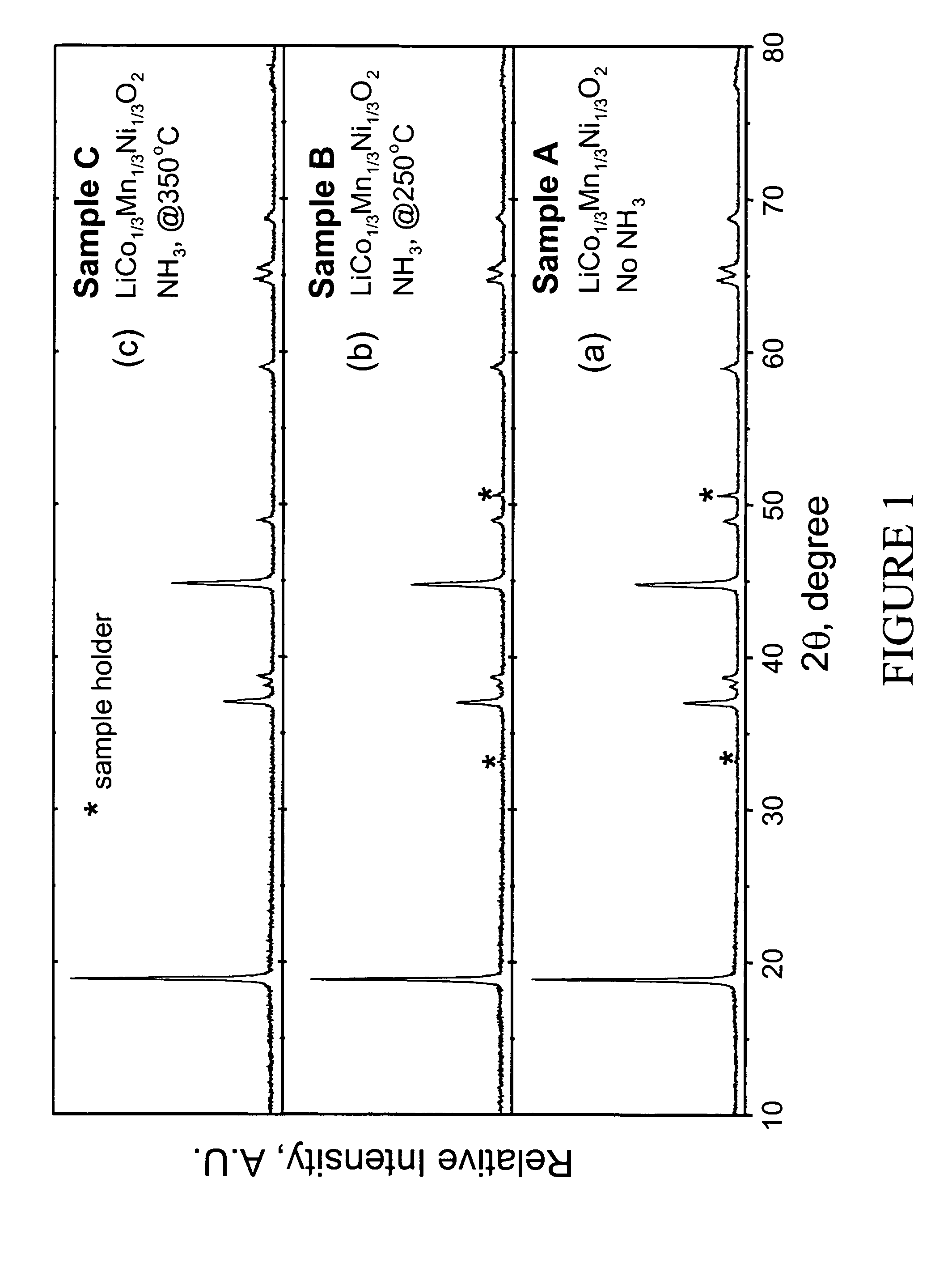
[0041]LiMn0.33Ni0.33Co0.33O2 powder was synthesized from LiOH.H2O and Mn0.33Ni0.33Co0.33(OH)x (x˜2) precursors. LiOH.H2O was used as supplied by Aldrich (98% pure). The Mn0.33Ni0.33Co0.33(OH)x precursor was prepared by coprecipitation of the required stiochiometric amounts of metal nitrates M(NO3)2.xH2O (M=Mn, Ni, and Co). After intimate mixing and grinding, the powdered mixture was pressed into a pellet and placed in a muffle furnace. A two-step heating procedure was used to fire the pellet according to the following procedure. First, a low temperature calcination step was performed at 480° C. for 5 hr. The pellet was then ground again and recompacted into pellet form. Second, a high temperature sintering step was performed at 900° C. for 3 hr followed by rapid quenching of the pellet between two copper plates. The pellet was ground a final time. Samples of the resulting LiMn0.33Ni0.33Co0.33O2 powder were heated at either 250 or 350° C....

example 2

Electrochemical Evaluation of LiMn0.33Ni0.33Co0.33O2 Electrodes

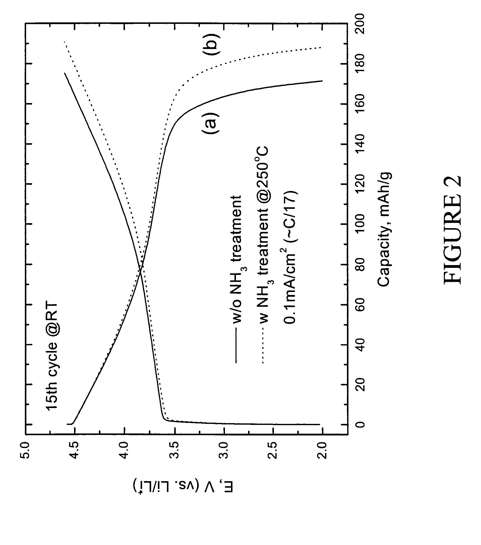
[0042]Electrochemical evaluation of LiMn0.33Ni0.33Co0.33O2 and preconditioned LiMn0.33Ni0.33Co0.33O2 positive electrodes was carried out as follows. The electrodes for the lithium cell were fabricated from an intimate mixture of 84 wt % of LiMn0.33Ni0.33Co0.33O2 electrode powder, 8 wt % polyvinylidene difluoride (PVDF) polymer binder (Kynar, Elf-Atochem), 4 wt % acetylene black (Cabot), and 4 wt % graphite (SFG-6, Timcal) slurried in 1-methyl-2-pyrrolidinone (NMP) (Aldrich, 99+%). An electrode laminate was cast from the slurry onto an Al current collector foil using a doctor-blade. The laminate was subsequently dried, first at 75° C. for 10 h, and thereafter under vacuum at 70° C. for 12 h. The electrolyte was 1M LiPF6 in ethylene carbonate (EC):diethyl carbonate (DEC) (1:1 mixture). The electrodes were evaluated at both room temperature and 50° C. in coin-type cells (size CR2032, Hohsen) with a lithium foil counter elec...

example 3

Synthesis of 0.3Li2MnO3.0.7LiMn0.5Ni0.5O2 Composite Electrodes

[0047]An electrode material with the composite formula 0.3Li2MnO3.0.7LiMn0.5Ni0.5O2 was prepared directly from Ni1−xMnx(OH)2 and LiOH.H2O precursors using the required Li:Mn:Ni ratio. The Ni1−xMnx(OH)2 precursor was prepared by precipitation from a basic LiOH solution of Ni(NO3)2 and Mn(NO3)2 (pH ˜11). The reagents were intimately mixed in an acetone slurry, dried in an oven overnight, and subsequently fired at 480° C. for 12 h and then at 900° C. for 5 h in air. Thereafter, the 0.3Li2MnO3.0.7LiMn0.5Ni0.5O2 product was rapidly quenched (also in air). The X-ray diffraction pattern of the resulting powder is shown in FIG. 8a (Sample D). The electrode powder was preconditioned according to the following procedures prior to cell assembly: 1) subjecting the powder to flowing NH3 gas in a tubular furnace at 200° C. for approximately 20 hrs, the X-ray diffraction pattern of this product being shown in FIG. 8b (Sample E); 2) wash...


PUM

PropertyMeasurementUnit
temperatureaaaaaaaaaa

Abstract

An uncycled electrode for a non-aqueous lithium electrochemical cell including a lithium metal oxide having the formula Li(2+2x) / (2+x)M′2x / (2+x)M(2−2x) / (2+x)O2−δ, in which 0≦x<1 and δ is less than 0.2, and in which M is a non-lithium metal ion with an average trivalent oxidation state selected from two or more of the first row transition metals or lighter metal elements in the periodic table, and M′ is one or more ions with an average tetravalent oxidation state selected from the first and second row transition metal elements and Sn. Methods of preconditioning the electrodes are disclosed as are electrochemical cells and batteries containing the electrodes.

Description

RELATED APPLICATION[0001]This application, pursuant to 37 C.F.R. 1.78(c), claims priority based on co-pending U.S. Provisional Application Ser. No. 60 / 465,034 filed on Apr. 24, 2003.CONTRACTUAL ORIGIN OF THE INVENTION[0002]The United States Government has rights in this invention pursuant to Contract No. W-31-109-ENG-38 between the U.S. Department of Energy and The University of Chicago representing Argonne National Laboratory.FIELD OF THE INVENTION[0003]This invention relates to improved lithium-metal-oxide positive electrodes for lithium cells and batteries, preferably rechargeable lithium-ion cells and batteries. These batteries are used to power a wide range of applications such as portable telecommunications equipment, computers, medical devices, electric vehicles and hybrid-electric vehicles. More specifically, the invention relates to lithium-metal-oxide electrodes with layered-type structures that are chemically preconditioned prior to cell assembly to improve the capacity, ...

Claims


Application Information

Patent Timeline
Patent Type & Authority Patents(United States)
IPC IPC(8): H01M4/48C01G45/12C01G53/04H01M4/50H01M4/52C01G53/00H01M4/02H01M4/04H01M4/131H01M4/485H01M4/505H01M4/525H01M10/052H01M10/36
CPCC01G45/1228C01G53/50H01M4/04H01M4/0471H01M4/131H01M4/485H01M4/505H01M4/525C01G45/125C01G51/50C01P2002/72C01P2002/77C01P2004/80C01P2006/40H01M10/052H01M2004/021Y02E60/122Y02T10/7011Y02E60/10
Inventor THACKERAY, MICHAEL M.KIM, JEOM-SOOJOHNSON, CHRISTOPHER S.
Owner UCHICAGO ARGONNE LLC
Learn More