Glass substrate and method of manufacturing the same

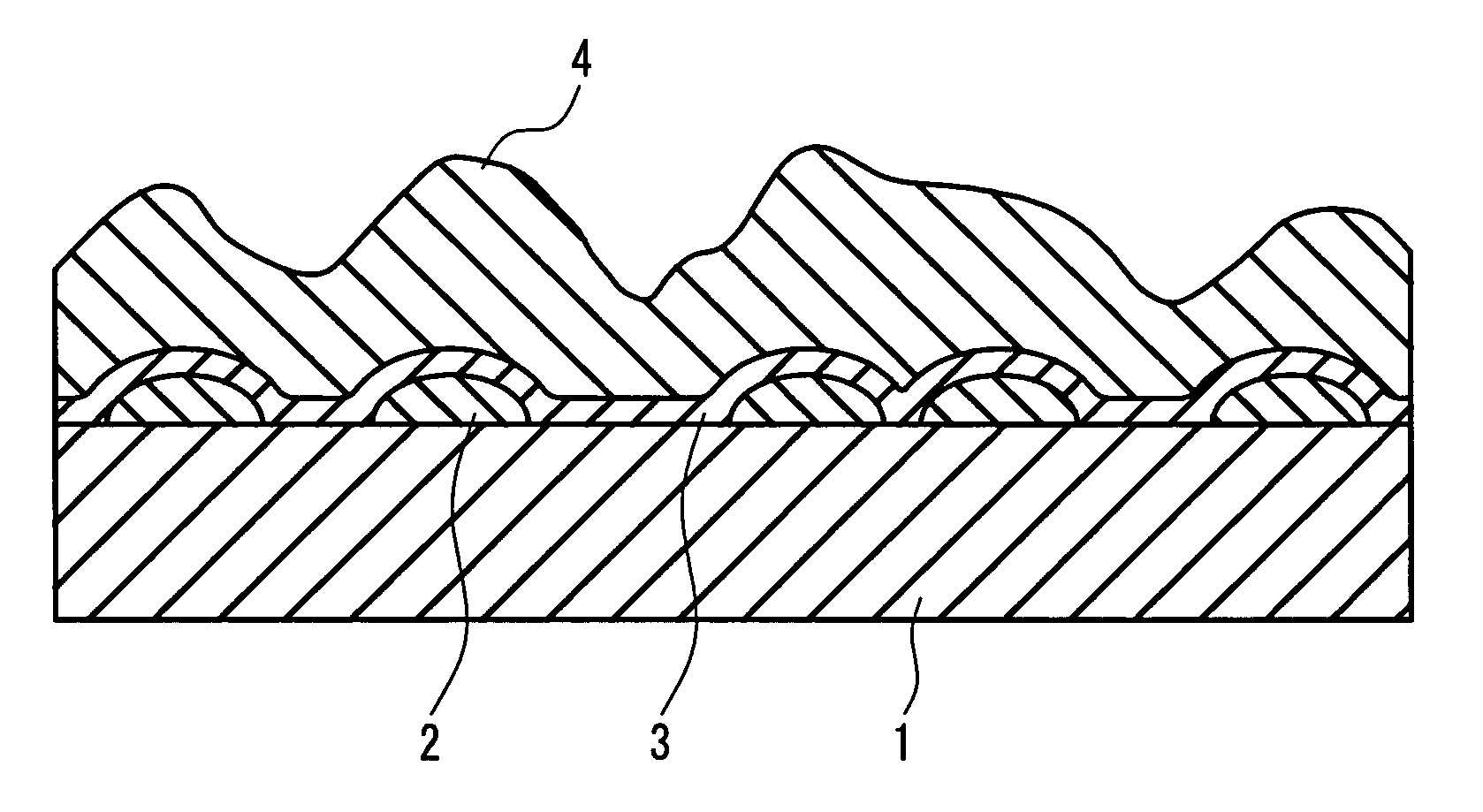
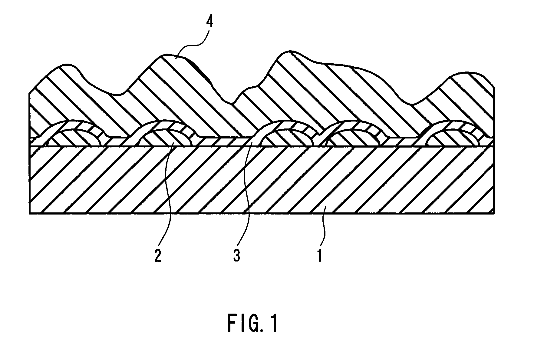
a technology of glass substrate and glass layer, which is applied in the field of glass substrate, can solve the problems of reducing the conductivity reducing the adhesion and high reflectance, and achieves the effect of easy manufacturing of such a glass substrate, light trapping, and large surface roughness of the transparent conductive film

Active Publication Date: 2008-01-22
NIPPON SHEET GLASS CO LTD
View PDF9 Cites 18 Cited by
  • Summary
  • Abstract
  • Description
  • Claims
  • Application Information

AI Technical Summary

Benefits of technology

[0010]In view of the foregoing problems, the present invention has been accomplished based on the findings obtained by the results of intensive research by the present inventors. It is an object of the present invention, in at least one preferred embodiment thereof, to provide, by controlling the shape of a first layer of an undercoating film formed on a glass surface, a low-reflectance glass substrate in which adhesiveness between a glass and a transparent conductive film is high, the surface roughness of the transparent conductive film is large, its light trapping effect is effectively exhibited, and its refractive index changes gradually. It is another object of the invention to provide a method capable of manufacturing such a glass substrate easily.

Problems solved by technology

When a transparent conductive film is formed directly on a glass surface, the adhesiveness of the transparent conductive film tends to be insufficient because of the difference in the thermal expansion coefficients and crystal morphologies, and a problem arises that the reflectance becomes high due to the high refractive index of the transparent conductive film.
Moreover, in the case of glass containing a large amount of alkaline component, such as a soda-lime glass composition, another problem arises that the alkaline component diffuses into the transparent conductive film over time, reducing the conductivity of the transparent conductive film, or reducing the adhesiveness thereof
However, according to the invention described in JP 2000-261013A, the roughness is formed only on the surface of the first layer of the undercoating layer, which has a thickness of several nanometers; therefore, the size of the roughness is not necessarily sufficient and there is room for improvement in terms of increasing the adhesiveness of the transparent conductive film.

Method used


Image

  • Glass substrate and method of manufacturing the same
  • Glass substrate and method of manufacturing the same
  • Glass substrate and method of manufacturing the same

Examples


example 1

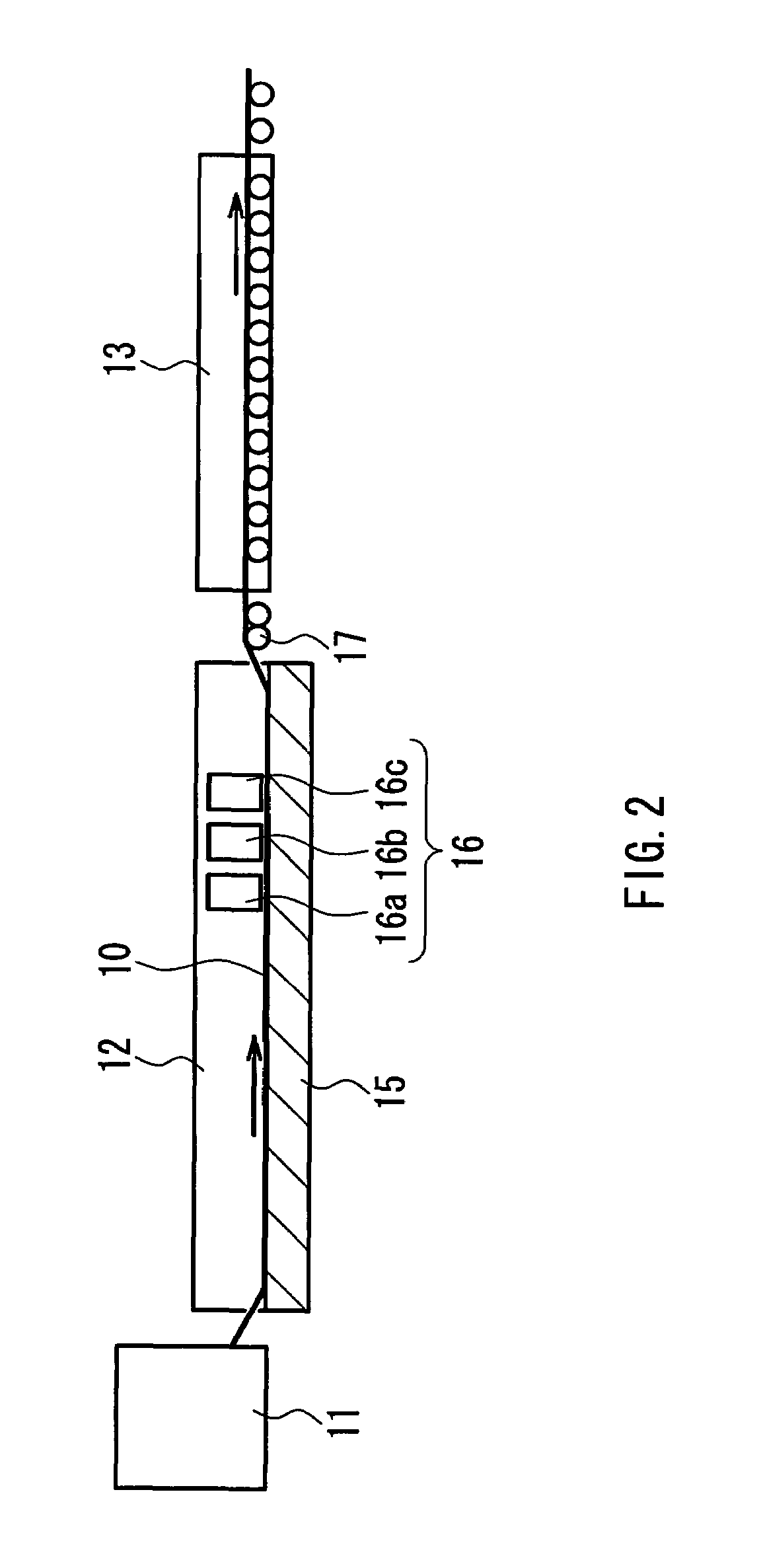
[0053]Various thin films were formed using an on-line CVD method with the following setting. Specifically, 98 volume % of nitrogen and 2 volume % of hydrogen were supplied to the interior space of a float bath so that the interior space of the float bath is kept at a slightly higher pressure than that outside the bath. With the interior of the bath being kept to be a non-oxidizing atmosphere, a mixed source gas composed of tin tetrachloride (vapor), oxygen, nitrogen, and helium was supplied from a first coater located on the most upstream side to form a group of separated and isolated metal oxide particles containing tin oxide as the main component on a glass ribbon. Table 1 below sets forth the concentration of tin tetrachloride and the concentration of oxidizing material of the mixed source gas supplied from the first coater, as well as the gas flow rate for blowing the mixed source gas against the glass ribbon and the surface temperature of the glass ribbon at that time.

[0054]Sub...


PUM

PropertyMeasurementUnit
heightaaaaaaaaaa
refractive indexaaaaaaaaaa

Abstract

The present invention provides a glass substrate including a glass sheet, a thin film containing silica as its main component, and a group of metal oxide particles separated from one another, the metal oxide particles and the thin film being stacked on the glass sheet in that order from the glass sheet side, wherein the average height of the metal oxide particles is 10 to 100 nm. The present invention also provides a method of manufacturing the glass substrate, the method including forming a group of metal oxide particles by a thermal decomposition method including an inorganic metal chloride as a raw material.

Description

[0001]This application is a continuation of international application Ser. No. PCTIJPO3 / 03578, filed Mar. 25, 2003.TECHNICAL FIELD[0002]This invention relates to a glass substrate that is suitable for window glass for buildings or vehicles and is provided with a surface film having a high visible light transmittance. The invention further relates to a method of manufacturing the glass substrate.BACKGROUND ART[0003]The surfaces of window glasses for buildings and vehicles are provided with a transparent conductive film for reducing the total solar light transmittance while maintaining high visible light transmittance for light that enters from outdoors, and for reflecting infrared rays that enter from the interior of rooms or vehicles. The transparent conductive film contains a metal oxide such as tin oxide, titanium oxide, zinc oxide, or indium oxide as its main component, and is usually doped with fluorine or the like in order to enhance its conductivity. Photoelectric conversion d...

Claims


Application Information

Patent Timeline
Patent Type & Authority Patents(United States)
IPC IPC(8): B32B17/06C03C17/00C03C17/34C23C16/40C23C16/44
CPCC03C17/007C03C17/3411C03C17/3417C23C16/401C23C16/407C03C2217/42C03C2217/77C03C2218/152
Inventor FUJISAWA, AKIRAKIYOHARA, KOICHIROICHIKI, KIYOTAKAYAMAMOTO, TORU
Owner NIPPON SHEET GLASS CO LTD
Why Eureka
Try Eureka