Optical deflection probe and optical deflection probe device

a probe device and optical deflection technology, applied in the direction of optical radiation measurement, instruments, counting objects on conveyors, etc., can solve the problems of inability to apply the probe to a region such as a blood vessel having a small inner diameter, inability to manufacture micromotors at very low cost, and inability to change and deteriorate with age. , to achieve the effect of simple configuration, low cost and low cos

Active Publication Date: 2008-01-29
SANTEC
View PDF4 Cites 49 Cited by
  • Summary
  • Abstract
  • Description
  • Claims
  • Application Information

AI Technical Summary

Benefits of technology

[0018]According to the present invention, since a signal light is deflected using excitation light transmitted via the optical fiber, it is unnecessary to provide an electrical power source for deflection and an additional cable. Furthermore, since the light is deflected by an optical deflector, the optical fiber need not be rotated resulting in an extreme simple configuration. Therefore, the present invention can provide the minute optical deflection probe and probe device and widely apply to the medical field. Since a rotating mechanism for the optical fiber becomes unnecessary, there occurs no accident of cutting the optical fiber. Further, since the probe is formed of a photoelectric conversion element and the optical deflector, the probe can be manufactured at very low cost. Thus, it is possible to provide a disposable probe.
[0019]Furthermore, the present invention can be also applied to various devices for deflecting light in a minute region in addition to the medical field. Moreover, the present invention can be applied to various devices to prevent change and deterioration with age by observing the state of materials in industrial products and equipment in a nondestructive manner and observing the cross section or tomographic layer of a minute area that is located beyond reach, such as in a pipe, or requires remote monitoring.

Problems solved by technology

However, when an optical fiber is rotated within twisted tracts in a living body, the optical fiber may be twisted and broken by undesired stress or torsion.
Furthermore, when the motor for rotating the mirror is provided in the probe, an electrical wire for driving needs to be additionally installed and thus, the probe cannot be applied to a region such as a blood vessel having a small inner diameter.
In addition, since a micromotor is expensive, disposable probes suitably used in the actual medical situation cannot be realized.

Method used


Image

  • Optical deflection probe and optical deflection probe device
  • Optical deflection probe and optical deflection probe device
  • Optical deflection probe and optical deflection probe device

Examples


first embodiment

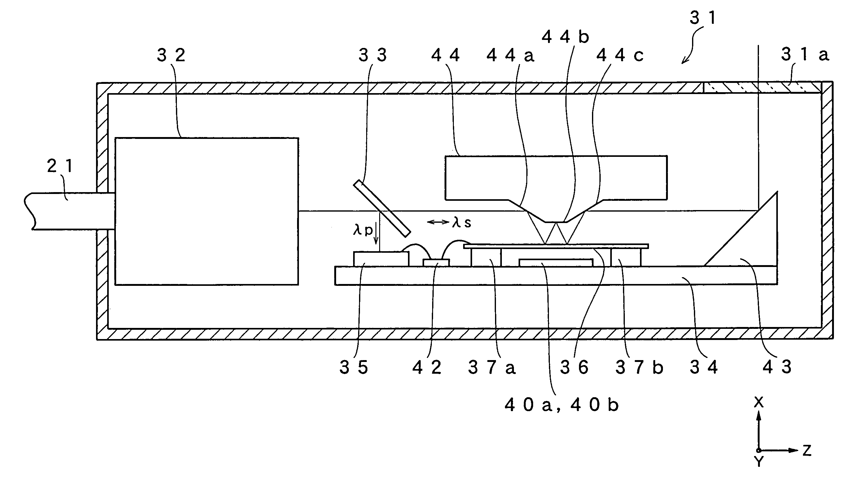
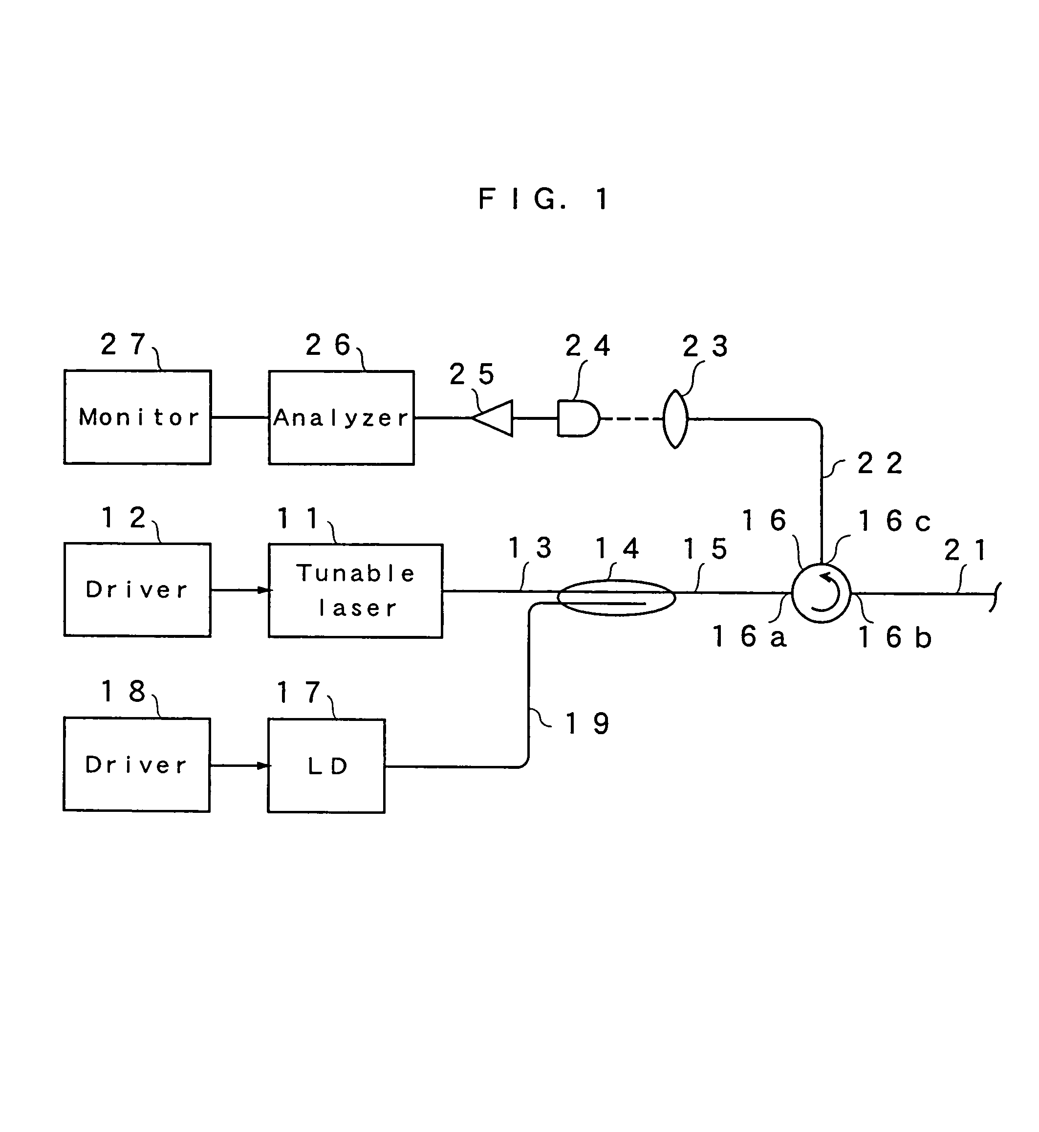
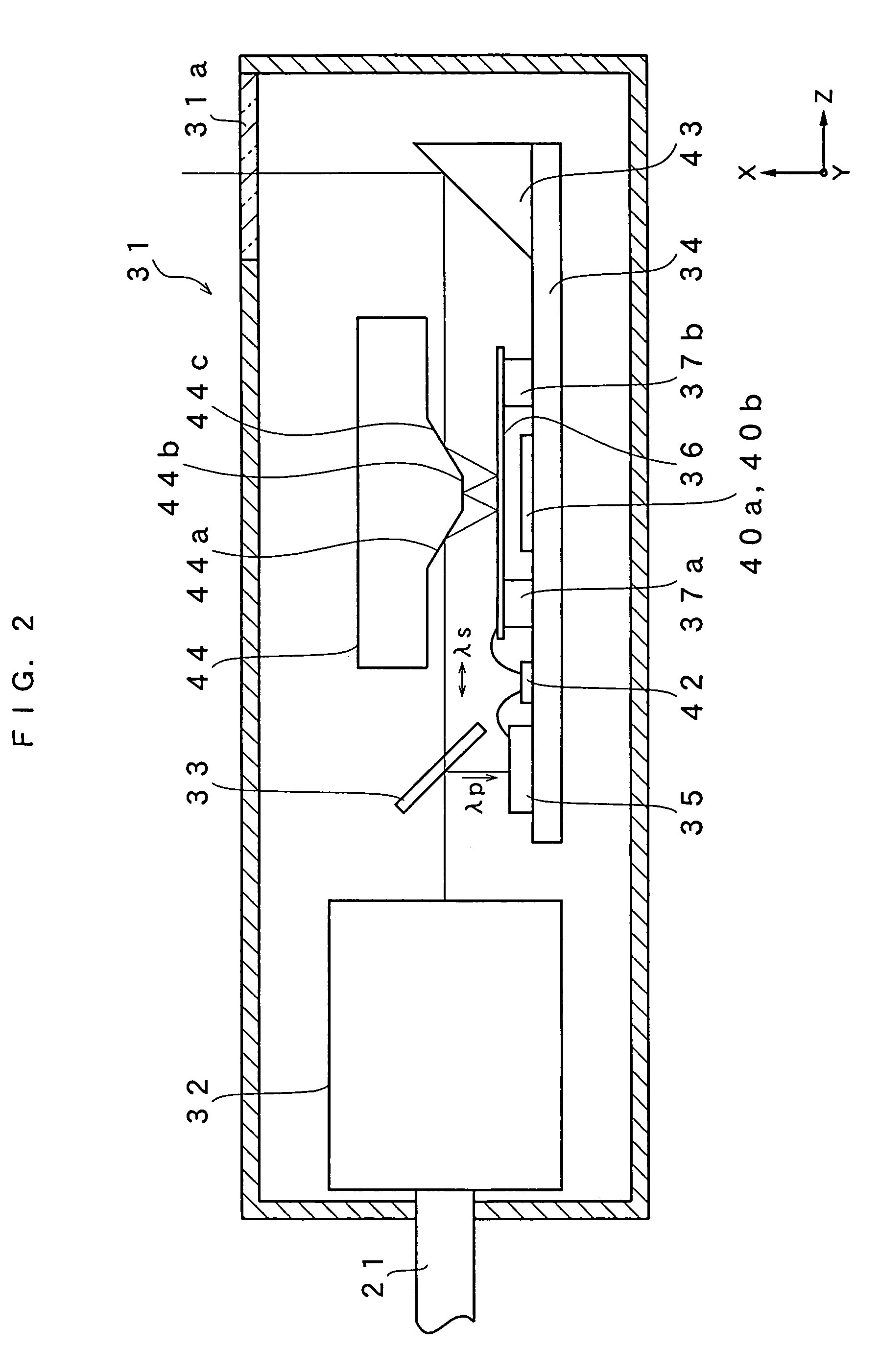
[0034]A first embodiment of the present invention will be described. FIG. 1 is a block diagram showing a configuration of a diagnosis device in accordance with the first embodiment. In FIG. 1, a tunable laser 11 is driven by a driver 12, outputs signal light having a wavelength of λs, for example, 1.3 μm band and forms a first light source together with the driver 12. The driver 12 periodically varies the wavelength of λs, for example, within the range of 100 nm. An output of the tunable laser 11 is supplied to an optical coupler 14 via an optical fiber 13. At the output side of the optical coupler 14 is provided an optical fiber 15, to which an optical circulator 16 is connected. The optical circulator 16 has terminals 16a, 16b and 16c. The light applied to the terminal 16a is emitted from the terminal 16b and the light applied to the terminal 16b is emitted from the terminal 16c. A laser diode 17 (LD) outputs excitation light having a waveband λp, for example, 1.55 μm band, which ...

second embodiment

[0045]Next, a second embodiment of the present invention will be described referring to FIGS. 6 to 8. FIG. 6 is a block diagram showing a configuration of the diagnosis device. The same reference numerals are given to similar components to those in the first embodiment and detailed description thereof is omitted. In this embodiment, the laser diode 17 and driver 18 are replaced with two laser diodes 17a, 17b and drivers 18a, 18b. The driver 18a and laser diode 17a constitute a second light source for generating a first excitation light of a first wavelength λp1. The laser diode 17b and driver 18b constitute a third light source for generating the second excitation light of a wavelength λp2. The drivers 18a, and 18b drive the laser diodes 17a and 17b respectively so that light intensity may vary in each different periods. The wavelengths λp1, λp2 are different from the signal light λs. For example, λp1 is set as 1510 to 1520 nm and λp2 as 1550 to 1560 nm. An optical coupler 14a combi...

third embodiment

[0051]Subsequently, a third embodiment will be described referring to FIG. 12. In the pres embodiment, the same reference numerals are given to similar components to those in the first embodiment and detailed description thereof is omitted. Although the MEMS type mirror is used in the first and second embodiments as an actuator, the minute mirror is deflected using a piezo type actuator in the present embodiment. FIG. 12 is a schematic view of an optical deflection probe using the piezo type actuator. In FIG. 12, as in the first embodiment, the optical filter 33 is set at the emitting side of the GRIN lens 32, reflects the excitation light thereon and lets the signal light pass through. A photo diode 35 is provided at the position at which the reflected light is received. In the present embodiment, as shown in the figure, a mirror 81 is rotatably held on a substrate 82 at the position at which the light passing through the optical filter 33 is reflected. A spacer 83 having a triangu...


PUM


Abstract

An optical fiber transmits signal light and the excitation light for driving an actuator each having a different wavelength to a probe. In the probe, the signal light and excitation light are separated from each other by an optical filter and the excitation light is irradiated to a photo diode. The signal light is supplied to a MEMS mirror unit. Then, the MEMS mirror unit is driven by an electromotive force obtained by the photo diode. In this manner, by modulating intensity of the excitation light, the signal light can be deflected.

Description

BACKGROUND OF THE INVENTION[0001]1. Field of the Invention[0002]The present invention relates to an optical deflection probe for deflecting a light beam to scan a measuring object and an optical deflection probe device using this probe.[0003]2. Discussion of the Related Art[0004]Devices for scanning a measuring object by deflecting a laser beam and for observing the state of the measuring object using a reflected light thereof have been conventionally used. Especially in a medical field, optical diagnosis is considered to be able to make a diagnosis requiring urgent treatment smooth and to observe a process during treatment in a noninvasive, in principle, manner without imposing a burden such as a pain on a client, and thus, expected to greatly contribute to medical care. According to such optical diagnosis, by inserting an optical probe or an endoscope into a living body, applying a signal light on a region of the living body via an optical fiber, propagating light returned backwar...

Claims


Application Information

Patent Timeline
Patent Type & Authority Patents(United States)
IPC IPC(8): H01J3/14H01J40/14H01J5/16
CPCG02B23/2423G02B26/0858
Inventor CHONG, CHANGHO
Owner SANTEC
Why Eureka
Try Eureka