Microcolumn-platform based array for high-throughput analysis

Inactive Publication Date: 2008-02-19
CORNING INC
View PDF15 Cites 28 Cited by
  • Summary
  • Abstract
  • Description
  • Claims
  • Application Information

AI Technical Summary

Benefits of technology

[0014]An advantage of the present invention is the possibility for physical agitation of a reaction solution to promote biological reactions. Since an array of microcolumns is physically a separate element from its corresponding micro-titer plate, it becomes possible to “stir” (i.e., move physically up and down, side to side, or swirl around) the solution within each well. This stirring action increases the microfluidic interactions of the immobilized biological probes and their targets. Conventional micro-titer plate techniques cannot perform this kind of physical agitation. Moreover, the present invention can operate at small volumes of reagents and samples most current micro-titer plate assays do. This provides savings in costs and conservation of scarce samples, since less reactants is needed to conduct an assay.
[0015]Further, according to another embodiment, micropins may be project away from the first surface of a microcolumn. A sample of biological material could be attached to the top surface of each micropin. Since each micropin has a minimal top surface area and does not have a peripheral region that may attract non-specific binding of target molecules, they offer the possibility of reducing background signal when imaging samples. Micropins raise the sample biosites above and away fro

Problems solved by technology

Fundamental constraints such as time or limited quantities of samples can affect the efficiency of analysis.
Current devices, although accurate and sensitive, are not conducive to the simultaneous, high-volume processing of many different assays of different experimental reagents or conditions in a single device.
This format permits analysis of many genes per sample, but unfortunately has not been conducive for high throughput analysis of many different samples under different, parallel assay conditions.
The multi-well format enables researchers to process samples in parallel under many different experimental conditions, but has been limited in the relatively low numbers of samples per well.
In the past, practical considerations, such as sample size, labor costs, and analysis time, placed l

Method used


Image

  • Microcolumn-platform based array for high-throughput analysis
  • Microcolumn-platform based array for high-throughput analysis
  • Microcolumn-platform based array for high-throughput analysis

Examples


example 1

[0102]To validate the concept of a microcolumn-based array platform, DNA microarray hybridization experiments were performed on glass microcolumns. The first surface of each glass microcolumn was polished and treated with a gama-amino propyl-trimethyl-silane (GAPS) coating. To compare glass slide and microcolumn formats, parallel microarray hybridization experiments were done on current GAPS-treated slides. Ten different PCR fragments, as indicated in Table 1, below, representing ten human genes were printed on glass microcolumns and on GAPS-coated slides using a Cartesian pin printer. The Cy3 and Cy5-cDNA probe ratios in hybridization mix was 1×=14 ng.

[0103]

TABLE 1NumberGeneCy5-labeled ProbeCy3-labeled Probe1AATK50x 1x2ABCD50x 1x3ACTB10x 1x4ADH210x 1x5AMPH5x1x6ANXA55x1x7AOC31x1x8API41x1x9BAD0x1x10 BCL2A0x1x

Table 2 summarizes the telative location of each of the PCR fragments on the microcolumn and slide.

[0104]

TABLE 2Genes Printed on ArraysKey to location of numberedGene Samples on ...

example 2

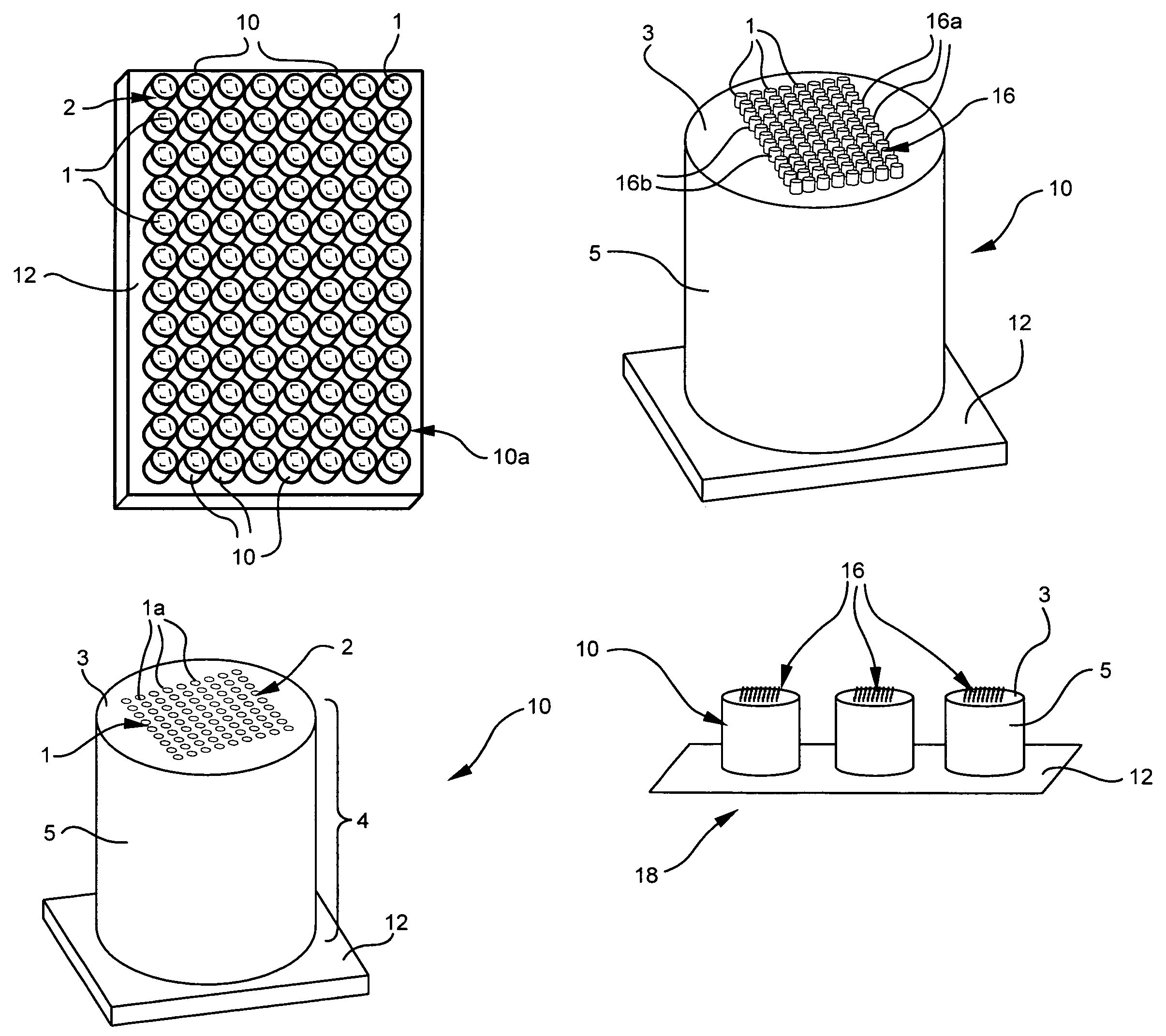
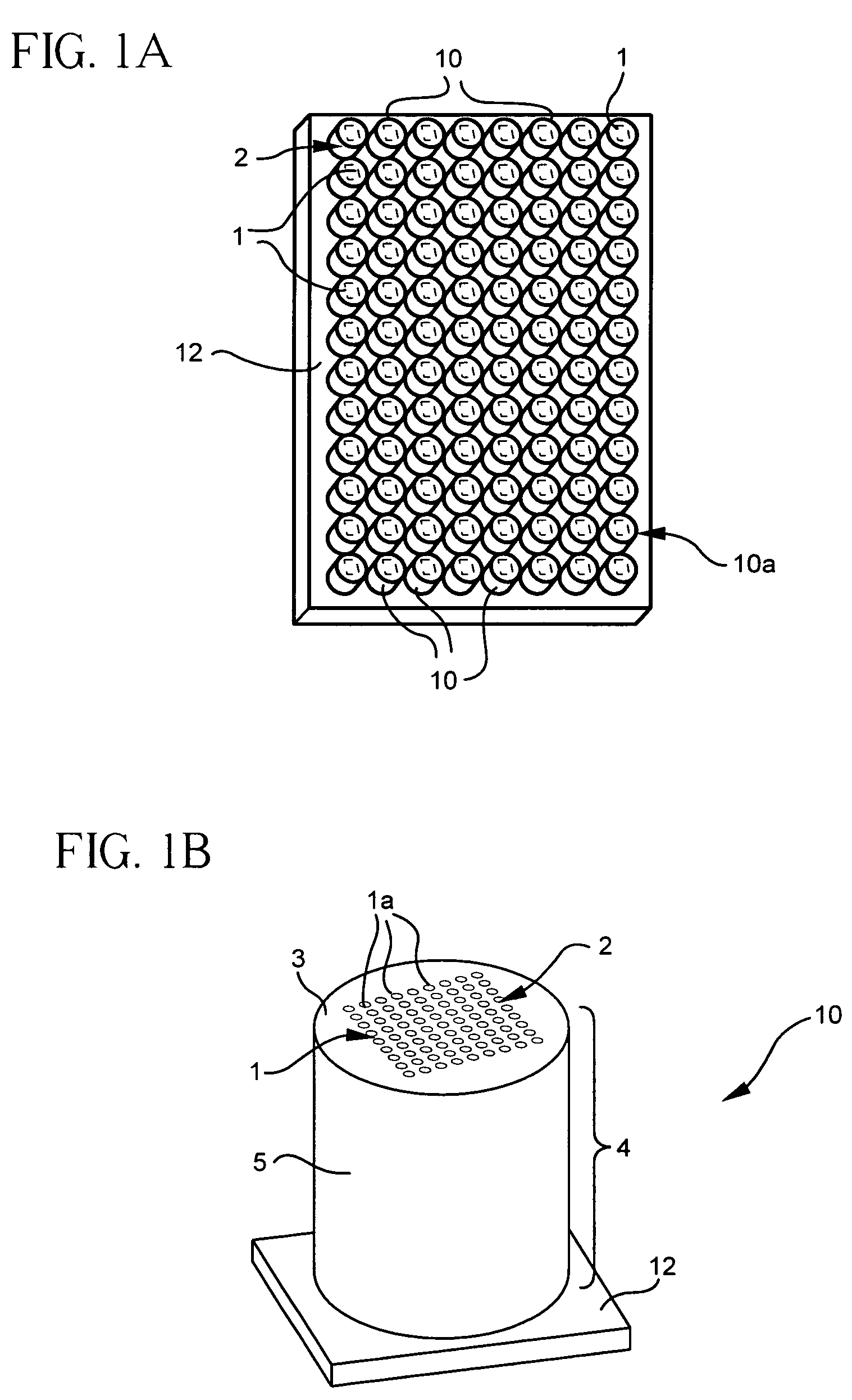
[0110]Use of the present microcolumn device in conjunction with a multiwell plate has at least two significant advantages. The advantages include the ability to minimize assay volumes and to increase assay sensitivity. Both of these features are related to the relatively small volume of the gap formed between the bottom surface of the well and the first surface of the microcolumn. For example, glass microcolumns according to the present invention, when inserted into corresponding silicone chambers (Vivascience, flexiPERM micro 12) having a GAPS-coated glass slide attached as the bottom surface of the chambers, forms a 175 μm gap between the opposing surfaces of the slide and the microcolumn. A small volume of solution is all that is required to fill the gap. A number of cDNA arrays, each with twenty-five gene spots, were printed on the GAPS-coated slides at locations corresponding to the chamber wells. Tables 4 and 5, respectively, summarize the identity and location of each gene on...

example 3

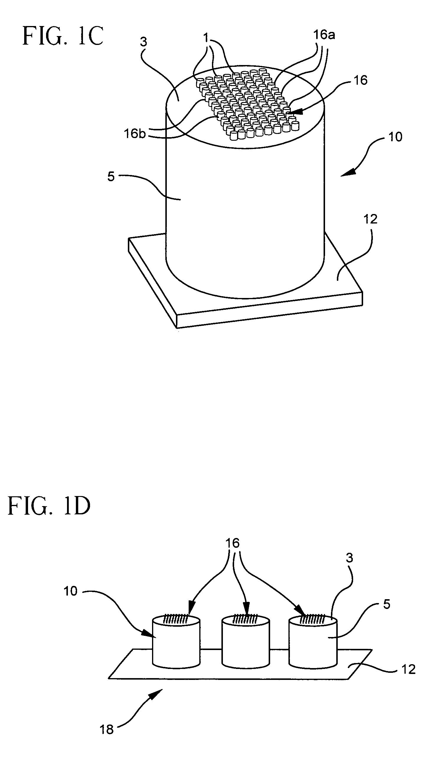
[0116]Further uses for the present microcolumn device include G-protein coupled receptor (GPCR) applications. Arrays of adrenergic β1 receptor (Biosignal Packard) were prepared on membranes and printed onto three adjacent microcolumns—using a robotic pin printer in a fashion like that described in U.S. patent application Ser. No. 09 / 854,786, “Arrays of Biological Membranes and Methods and Use Thereof,” by Lahiri et al., which is incorporated herein by reference. These glass microcolumns were coated with a thin gold layer and functionalized with GAPS. The particular description about the chemical preparation, deposition, and reaction of functionalized gold coatings is detailed also in U.S. patent application Ser. No. 09 / 854,786. Functionalized gold surfaces have been shown to yield signal-to-noise ratios that are far superior to ordinary, uncoated glass surfaces. To assay ligand binding, the microcolumns were inserted into the wells of an 1×8-Stripwell plate (Corning®) containing a f...


PUM

PropertyMeasurementUnit
Fractionaaaaaaaaaa
Diameteraaaaaaaaaa
Lengthaaaaaaaaaa

Abstract

A device and methods for performing biological or chemical analysis is provided. The device includes an array of three-dimensional microcolumns projecting away from a support plate. Each microcolumn has a relatively planar, first surface remote from the support plate. An array of multiple, different biological materials may be attached to the first surface. The device, when used in combination with existent micro-titer well plates, can improve efficiency of binding assays using microarrays for high-throughput capacity.

Description

CLAIM OF PRIORITY[0001]The present Application claims priority to U.S. Provisional Application No. 60 / 317,660, filed on Sep. 7, 2001, in the name of Michael D. Brady et al., the content of which is incorporated herein by reference.FIELD OF TECHNOLOGY[0002]The present invention relates to an apparatus and method for biological analysis. In particular, the invention pertains to arrays of three-dimensional elevated surfaces, which may be used in combination with existent micro-titer well plates for performing high-throughput assays or other biological experiments.BACKGROUND[0003]The proliferation of biological targets and candidate drug compounds in high-throughput screening and the increased interest in characterizing the human genome have created a high demand for rapid, efficient, and reproducible study of many genes and the proteins for which they encode. Fundamental constraints such as time or limited quantities of samples can affect the efficiency of analysis. Current devices, al...

Claims


Application Information

Patent Timeline
IPC IPC(8): C12M1/34G01N33/53B01L3/00C12M1/00C12N15/09C12Q1/68C12Q1/6837C40B60/14G01N33/543G01N33/566G01N35/02G01N37/00
CPCB01L3/5025B01L3/50853C12Q1/6837G01N33/54366G01N33/54373G01N33/54386G01N35/028B01J2219/00317B01J2219/00504B01J2219/00511B01J2219/00585B01J2219/00605B01J2219/0061B01J2219/00612B01J2219/00619B01J2219/00621B01J2219/00626B01J2219/00637B01J2219/00653B01J2219/00662B01J2219/00707B01L2200/025B01L2200/026B01L2300/046B01L2300/0636B01L2300/0829C40B60/14
Inventor WEBB, BRIAN L.PENG, JINLINBRADY, MICHAEL D.DESPA, MIRCEAHORN, KEITH A.LAHIRI, JOYDEEPROOT, DAVID M.STAMATOFF, JAMES B.YUEN, PO KI
Owner CORNING INC
Why Eureka
Try Eureka