Laser cutting apparatus with a high quality laser beam

a laser cutting and laser beam technology, applied in the direction of digital signal error detection/correction, instruments, recording signal processing, etc., can solve the problems of inability to focus the laser beam, difficulty in adequately providing an assist gas to the cutting groove, and difficulty in cutting, etc., to achieve the effect of large thickness

Inactive Publication Date: 2008-03-25
FANUC LTD
View PDF19 Cites 23 Cited by
  • Summary
  • Abstract
  • Description
  • Claims
  • Application Information

AI Technical Summary

Benefits of technology

[0018]It is an object of the present invention to solve the above-described problems associated with prior art, and to provide a laser cutting apparatus capable of properly cutting a workpiece having a large thickness with a laser beam, without changing the constitution of a processing nozzle and / or a collective lens.

Problems solved by technology

There may be a case, however, wherein the laser beam cannot be focused, depending upon the energy distribution thereof, into a spot at the diffraction limit.
There is a problem, when such a thick plate is to be cut using a laser, of the difficulty in adequately supplying an assist gas to a cutting groove.
As the thickness of the plate increases, the oxygen assist gas supplied to the surface of the steel plate is exhausted midway in the thickness direction so that, near the back surface of the steel plate, the cutting becomes difficult due to a deficiency of oxygen.
If, at this time, the pressure of the supplied oxygen gas is increased to increase the amount of supply, the flow rate of the assist gas is excessively increased so that an anomalous combustion (or a self-burning phenomenon) takes place at the front surface of the steel plate.
As a result, surface quality of the cut section may be deteriorated, or dross may be accumulated to degrade the function of the products.
Also, in the case where nitrogen or argon gas, that does not generate heat from a combustion reaction, is used as the assist gas, if the thickness of the workpiece is increased, the flow rate tends to be reduced midway in the thickness direction of the workpiece, and the power for blowing away the molten metal, etc. tends to become inadequate.
In the case of non-metallic material, the function of the assist gas, as a cooling gas to suppress carbonization or excessive melting, tends to be impaired by the decrease in the flow rate.
However, an optimum design is generally difficult with the technique of controlling the flow of the assist gas by suitably designing the nozzle shape, etc.
When above-described method is applied, for example, to the cutting of the steel plates with oxygen as assist gas, however, the expected result can only be obtained for thicknesses in the range of 12 mm to 16 mm, and the advantage of the ring mode over Gaussian mode can hardly be recognized at thickness greater than 20 mm.

Method used


Image

  • Laser cutting apparatus with a high quality laser beam
  • Laser cutting apparatus with a high quality laser beam
  • Laser cutting apparatus with a high quality laser beam

Examples


Embodiment Construction

[0035]The embodiments of the present invention are described below in detail, with reference to the accompanying drawings. In the drawings, the same or similar components are denoted by common reference numerals.

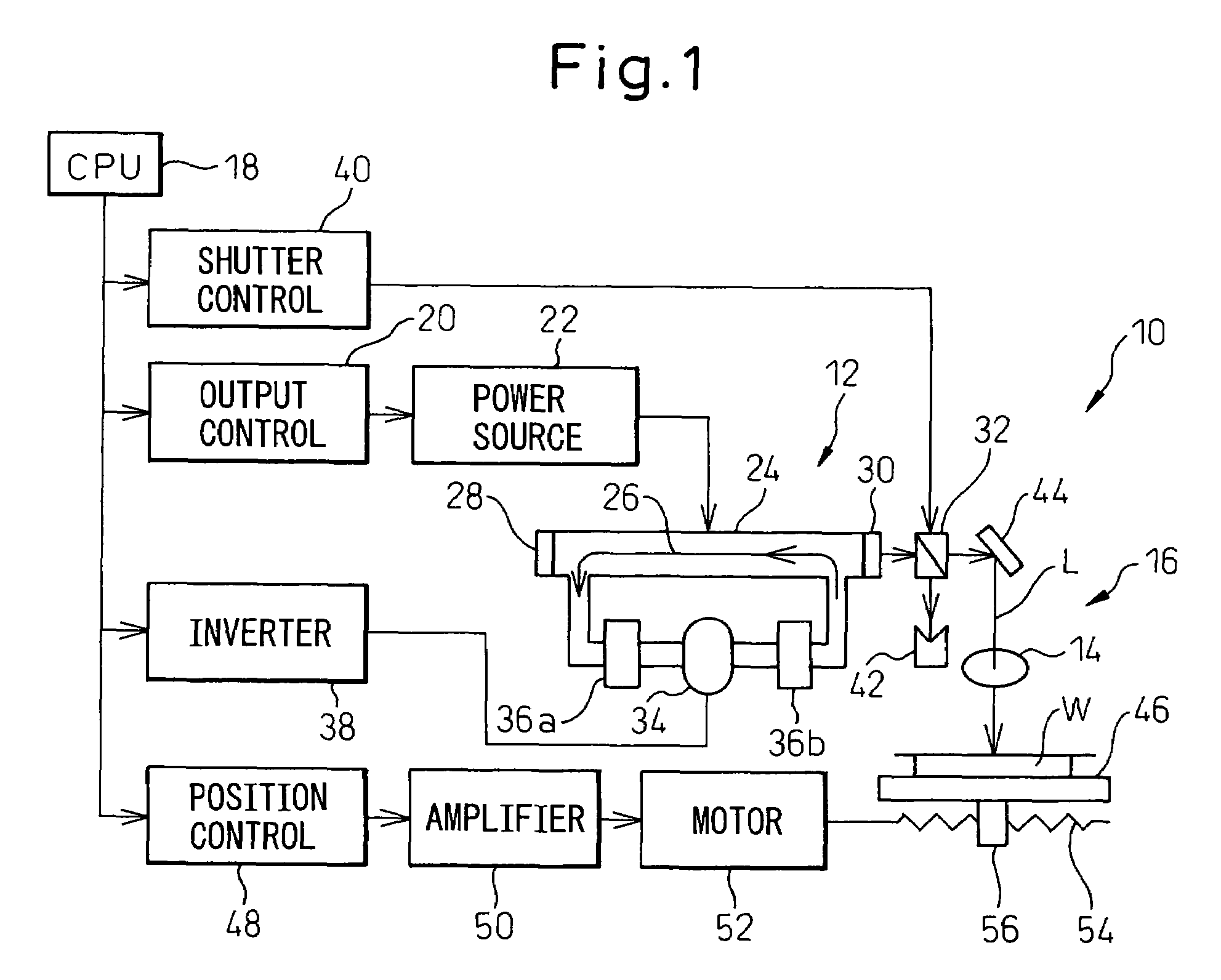
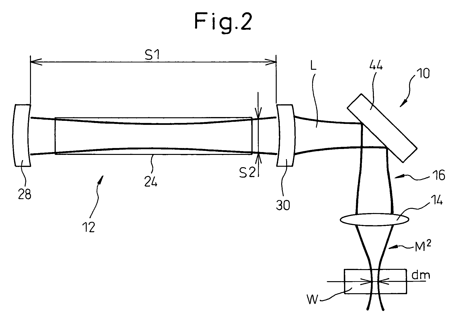
[0036]Referring to the drawings, FIG. 1 shows the general configuration of a laser processing system including a laser cutting apparatus 10 according to an embodiment of the present invention, and FIG. 2 schematically shows the basic configuration of the laser cutting apparatus 10 of FIG. 1.

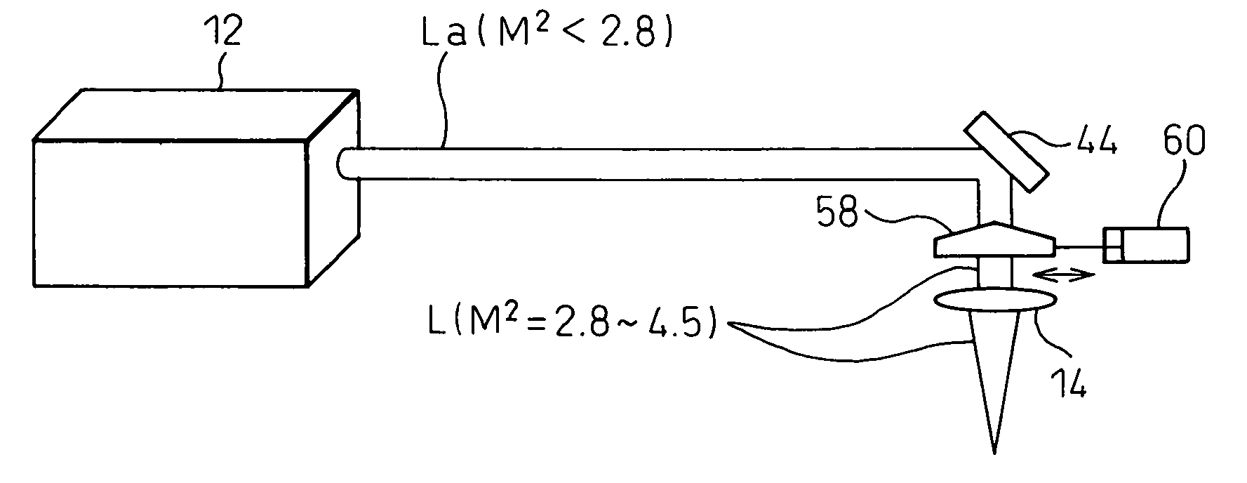
[0037]As shown in FIG. 2, the laser cutting apparatus 10 according to the present invention includes a gas laser oscillator 12, and an optical system 16 including a collective lens 14 and transmitting and collecting a laser beam L generated in the gas laser oscillator 12 to irradiate a workpiece W with the laser beam L. The laser cutting apparatus 10 is constructed such that an index M2 for evaluating collecting properties (hereinafter referred to as a beam quality) of the laser beam L em...


PUM

PropertyMeasurementUnit
diameteraaaaaaaaaa
diameteraaaaaaaaaa
diameteraaaaaaaaaa

Abstract

A laser cutting apparatus capable of properly cutting a workpiece having a large thickness with a laser beam. The laser cutting apparatus includes a gas laser oscillator; and an optical system including a collective lens and transmitting and collecting a laser beam generated in the gas laser oscillator to irradiate a workpiece with the laser beam. An index M2 for evaluating a beam quality of the laser beam emerging from the optical system, with which the workpiece is irradiated, is in a range of 2.8 to 4.5; while the index M2 is defined by a formula: M2=π×(dm)2 / (4×λ×Zr); in which λ is a wavelength of the laser beam; dm is a minimum beam diameter of the laser beam in a predetermined optical-path range including a focal point of the collective lens; and Zr is a distance between a first position on an optical axis, at which the minimum beam diameter dm is established, and a second position on the optical axis, at which a beam diameter “21 / 2×dm” is established, in the laser beam in the predetermined optical-path range.

Description

BACKGROUND OF THE INVENTION[0001]1. Field of the Invention[0002]The present invention relates to a laser cutting apparatus.[0003]2. Description of the Related Art[0004]A cutting and machining process, for a metal or resinous material and using a laser beam, has been widely conducted. A laser apparatus for a cutting process generally includes a laser oscillator, as a source of a laser beam, an optical system (or a light guide system) for transmitting and collecting the laser beam onto a material to be processed (i.e., a workpiece), a mechanical driving system for scanning the spots to be irradiated with the beam on the workpiece, a control system for controlling the laser oscillator or the mechanical driving system, and auxiliary apparatuses such as a coolant supply apparatus, an assist gas feeding apparatus, etc.[0005]In general, a laser cutting apparatus of this type is considered to have a higher machining capability when the collecting properties (i.e., a beam quality) of a laser...

Claims


Application Information

Patent Timeline
Patent Type & Authority Patents(United States)
IPC IPC(8): B23K26/06B23K26/38B23K26/064
CPCB23K26/06B23K26/0643B23K26/0648B23K26/0665B23K26/38B23K26/14
Inventor EGAWA, AKIRAANDO, MINORUMORI, ATSUSHI
Owner FANUC LTD
Why Eureka
Try Eureka