
Diffusion bonding for metallic membrane joining with metallic module

a technology of metallic membrane and metallic module, which is applied in the direction of manufacturing tools, non-electric welding apparatus, and welding apparatus, etc., can solve the problems of argon arc welding generally unsatisfactory for welding thin pd-based membranes with metallic modules, degrade or destroy the strength, ductility, and other metallurgical properties of the membrane, and achieve the effect of reducing the cost of argon arc welding

Active Publication Date: 2008-04-08
NORAM ENG & CONSTRS
View PDF19 Cites 13 Cited by
  • Summary
  • Abstract
  • Description
  • Claims
  • Application Information

AI Technical Summary

Benefits of technology

"This patent describes a method of bonding metallic parts together using a metallic membrane. The method involves pressing the membrane against the metal parts, heating them to a high temperature, and subjecting them to a controlled gas environment. The pressure can range from 100 to 10,000 psig. The method can be carried out for at least 4 hours and can involve heating the parts to a temperature of between 500 to 1,100°C. The membrane can be made of palladium or a palladium-silver alloy. The gas can be hydrogen, an inert gas, or a mixture of both. The method can also involve polishing the surfaces of the metal parts before pressing them together. The technical effect of this patent is to provide a reliable and effective method for bonding metallic parts together using a metallic membrane."

Problems solved by technology

Even though Pd-silver (Ag) alloy foil or tube membranes are commercially available on a large scale, application of Pd—Ag membranes and foils encounter obstacles due to the lack of a satisfactory technique for joining the Pd—Ag alloy to normal metallic modules, such as to a stainless steel reactor or a separation cell.
Argon arc welding is generally unsatisfactory for welding thin Pd-based membranes with metallic modules because the high temperatures required for argon arc welding cause distortion and degrade or destroy the strength, ductility, and other metallurgical properties of the membrane.
The high welding temperature can cause the membrane to be oxidized.
The welded area can experience a hydrogen embrittlement problem.
However, when electronic beam welding is used to join a membrane with metallic module, micro-cracks in and near the welding area are often present that can cause leakage over time.
The melting point of Cu—Ag alloy is high (>780° C.) and the Cu—Ag brazing filler can damage to the Pd—Ag alloy membrane.
The melting point of Au is high (1064.43° C.) and can damage the Pd—Ag alloy.
Thermal treatment of cold-worked alloys at high temperatures can cause significant boundary growth.
Both boundary growth and concentration of impurities in the boundary area can lead to the formation of defects, which reduce the selectivity and longevity of the membrane.
This contaminates the membrane during brazing or during subsequent use of the membrane at high temperatures in hydrogen.
Instability of the graphite in oxidizing or steam environments and difficulty making a gas-tight graphite make this method difficult to scale up.

Method used


Image

  • Diffusion bonding for metallic membrane joining with metallic module
  • Diffusion bonding for metallic membrane joining with metallic module
  • Diffusion bonding for metallic membrane joining with metallic module

Examples


example 2

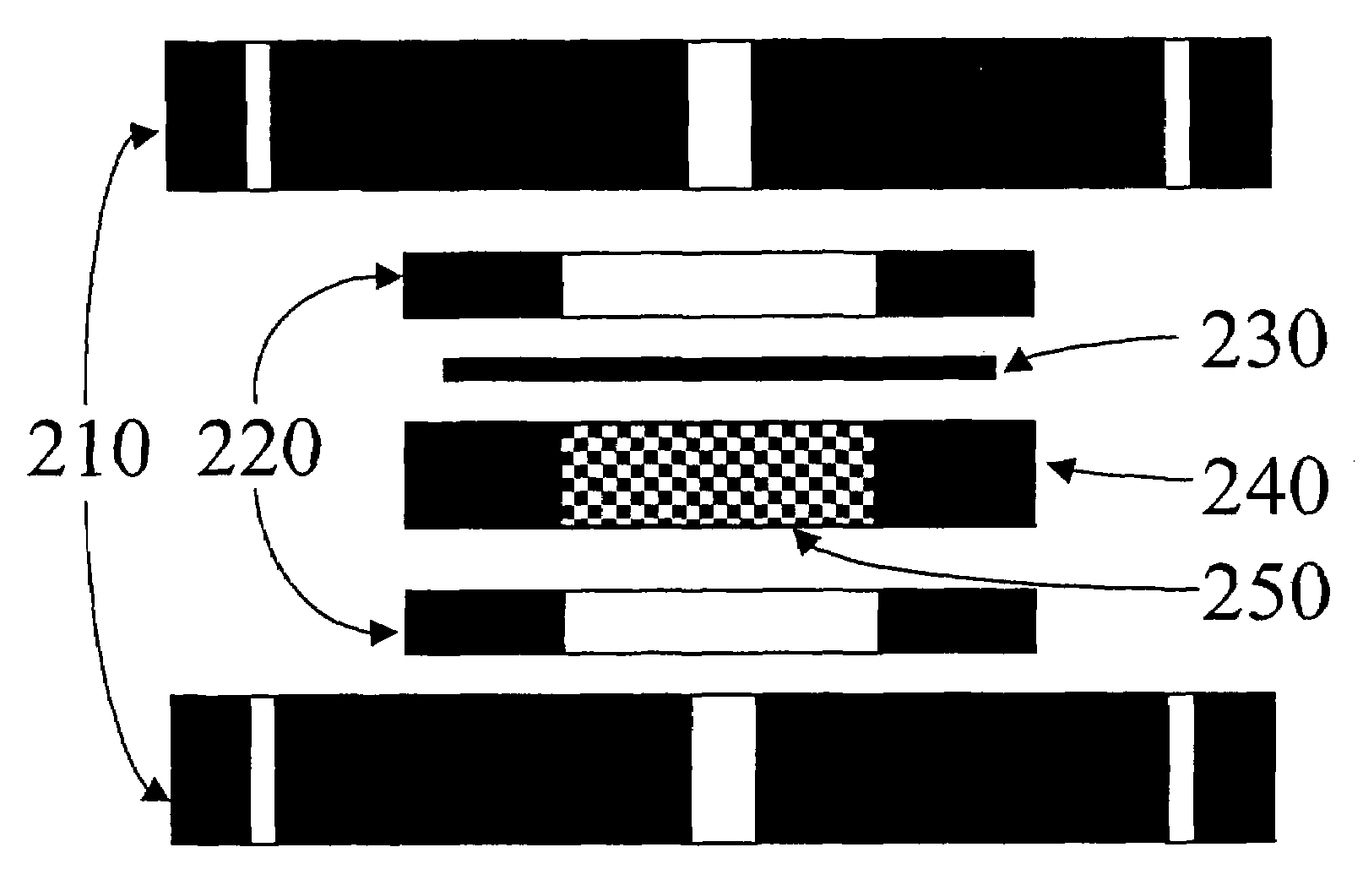
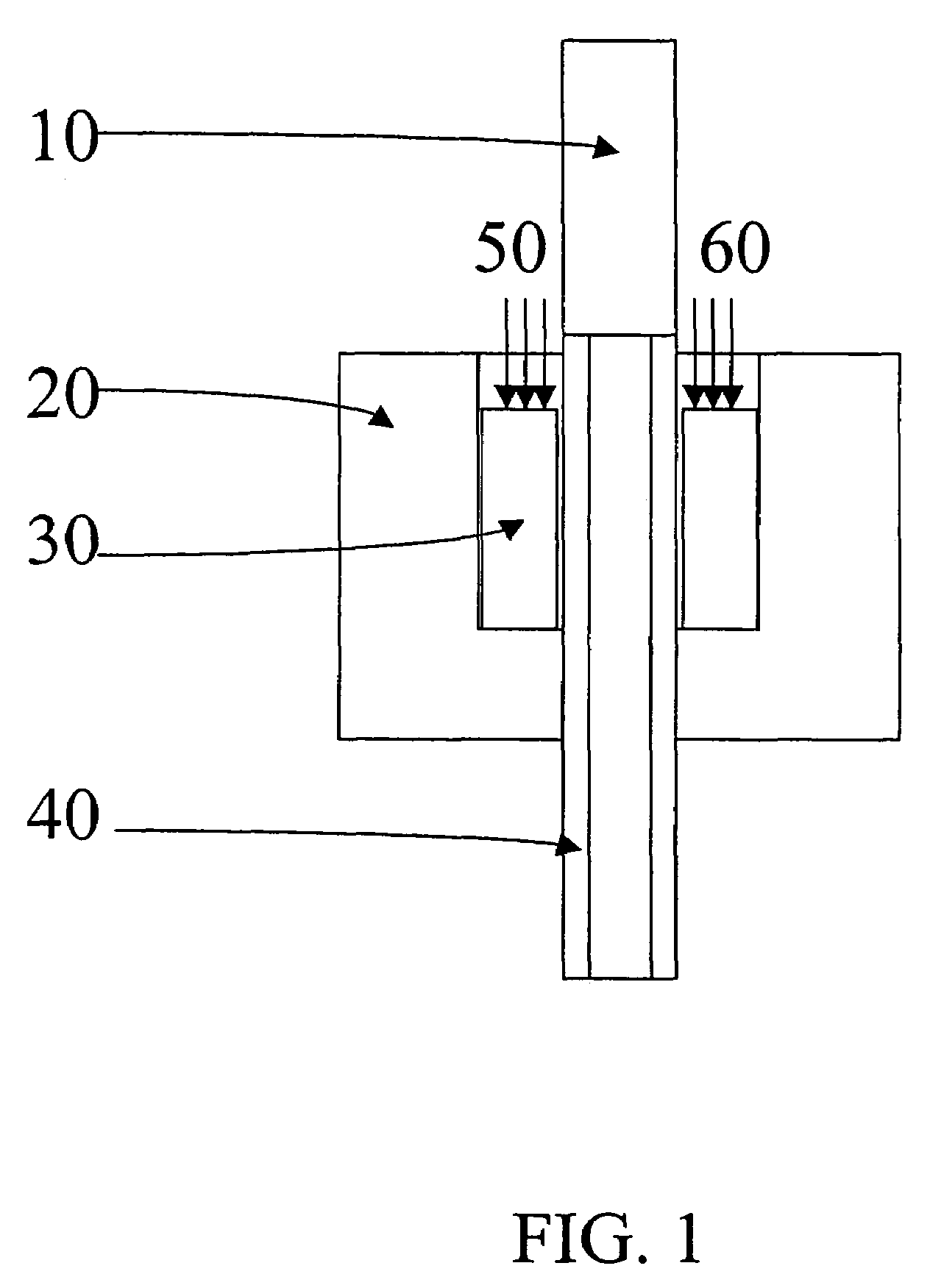
[0050]Joining a circular Pd-5% / wt Ru alloy disc 230 with a stainless steel wafer 240. The process was performed with a stainless steel 304 wafer 240 having an outside diameter of 2″, an inside diameter of 1″ and a thickness of 1 / 16″ was punched from a sheet. One surface of the wafer 240 was polished with grit 600 sandpaper and then buffered and cleaned. A Pd-5% / wt Ru alloy disk 230 with a diameter of 1.75″ and a thickness of 50 μm was placed on the cleaned surface. After compression with up to 3000 psig mechanical pressure through the flanges by torque load as shown in FIG. 3, the apparatus was baked in a vessel at 650° C. for 24 hr under 15 psig hydrogen. After properly cooling down, the joined disk was taken out and welded with a stainless steel flange 320 to form a membrane module as shown in FIG. 4, where the membrane foil was properly supported by a porous substrate.

[0051]FIG. 4 is a cross-sectional view of a Pd—Ru alloy membrane module 310 after diffusion bonding with a stainl...

example 3

[0054]Joining a Pd sheet 420 with a stainless steel frame. A 3.25″ by 6.25″ stainless steel 304 sheet with a thickness of 1 / 16″ with a cut away rectangle 430 in its middle to form a frame 410 whose width is 0.625″, as shown in FIG. 5. One surface of the sheet was polished with grit 600 sandpaper and then buffered and cleaned. A 3″×6″ palladium sheet with a thickness of 47 μm was placed on the cleaned surface. After properly compressed up to 3000 psig mechanical press, the apparatus was baked in a vessel at 650° C. for 24 hr under 15 psig hydrogen. After properly cooling down, the joined parts were taken out and welded to a stainless steel flange to form a membrane module, where the membrane foil was supported by a porous substrate. The bond withstood strength and gas-tight testing as described in example 1.

example 4

[0055]Joining a circular 75% / wt Pd-25% / wt Ag alloy disc with a stainless steel wafer at a higher temperature for a shorter time. A similar joining method was used as in example 1 except that membrane foil was 75% / wt Pd-25% / wt Ag alloy and that the bonding process was carried out at 700° C. for 5 hr. The bond withstood strength and gas-tight testing as described in example 1.


PUM

PropertyMeasurementUnit
pressureaaaaaaaaaa
temperatureaaaaaaaaaa

Abstract

This invention relates to a method of bonding a metallic membrane with metallic part involving pressing a smooth surface of the metallic membrane against the smooth surface of the metallic part, and heating the metallic membrane and metallic part to a temperature above the half melting point of the metallic membrane while subjecting the metallic membrane and metallic part to a controlled environment of a proper gas atmosphere. The metallic membrane can comprise palladium and the pressurized gas can comprise one of hydrogen, an inert gas or their mixture.

Description

TECHNICAL FIELD[0001]The invention relates to fabrication of joints between metal components, particularly between metallic membranes and metallic modules.BACKGROUND[0002]As new materials are developed, it is advantageous to be able to weld or otherwise join the new material to itself or to already existing materials. Achieving satisfactory joint quality is an important milestone in a research and development scheme for any new material as satisfactory joint quality increases the likelihood that the new material can be used for widespread applications.[0003]The production, separation and purification of hydrogen is an important industrial process, in part due to a continuing and increasing demand for hydrogen in electronic, fuel cell and chemical industries. Metallic membranes having high permselectivity, such as palladium (Pd) based membranes, are extensively used in the research and development of hydrogen production and separation. Even though Pd-silver (Ag) alloy foil or tube me...

Claims


Application Information

Patent Timeline
Patent Type & Authority Patents(United States)
IPC IPC(8): B23K20/00B01D65/00B01D71/02B23K20/02B23K20/22C01B3/50
CPCB01D65/003B01D67/0055B01D69/145B01D71/022B23K20/02B23K20/22C01B3/505B23K2203/00C01B2203/041C01B2203/047C01B2203/0475C01B2203/048C01B2203/0495B23K2103/05B23K2103/08B23K2103/18Y02E60/50B01D71/02231
Inventor LI, ANWU
Owner NORAM ENG & CONSTRS
Learn More