Programmable mask and method for fabricating biomolecule array using the same

a biomolecule array and programable mask technology, applied in the direction of nucleotide libraries, radiofrequency controlled devices, instruments, etc., can solve the problems of limited reservoirs which can be provided to robots, the number of arrays per unit area cannot be increased, and the cost is high, so as to achieve the effect of high density and easy stripping

Inactive Publication Date: 2008-04-22
ELECTRONICS & TELECOMM RES INST
View PDF15 Cites 5 Cited by
  • Summary
  • Abstract
  • Description
  • Claims
  • Application Information

AI Technical Summary

Benefits of technology

[0019]Thus, the object of the present invention is to provide a LCD type programmable mask in which the protection group within a specific cell on a sample substrate can be readily stripped and the illumination dose of the light can be adequately adjusted so that the biomolecule array having high density can be fabricated.
[0020]The another object of the present invention is to provide a method for fabricating the biomolecule array having high density by using said programmable mask.

Problems solved by technology

However, this method has a demerit which the number of the arrays per the unit area can be not increased.
In this method, every sample solution needs the reservoir, but the number of the reservoirs which can be provided to the robot is limited.
However, since a plurality of photomask are required, this method brings out a problem that it takes much time and cost.
This method brings out problems that the complex optical system is required and only a mosaic pattern can be obtained.
Such electrode addressing method brings out problems that it can be not applied to the case where a number of arrays are used and a microelectrode array is required.
However, in this method, there is a problem that the yield of each reaction is low, thereby the degree of purity of each cell is low.
However, the LCD type programmable mask has problems in a point of view of polarization, UV transmission, and deactivation due to ultraviolet light.
First, since the light output from the general LCD is polarized and the protection group on the substrate generally exists therein without orientation, every protection group exist in a specific cell on the substrate can not be stripped by the light output from the LCD.
Also, since the amorphous silicon transistor has dark-conductivity higher than photo-conductivity by 106 times, it can not function as a switching element, thereby the arranged state of the liquid crystal can not be adjusted.

Method used


Image

  • Programmable mask and method for fabricating biomolecule array using the same
  • Programmable mask and method for fabricating biomolecule array using the same
  • Programmable mask and method for fabricating biomolecule array using the same

Examples


Embodiment Construction

[0034]Hereinafter, the preferred embodiments of the present invention will be explained with reference to the accompanying drawings. However, these embodiments are provided so that those skilled in the art can understand the present invention and it may be variously changed, and the present invention should not be understood as limited to the specific embodiments thereof. In figure, the same reference numeral indicates the same element.

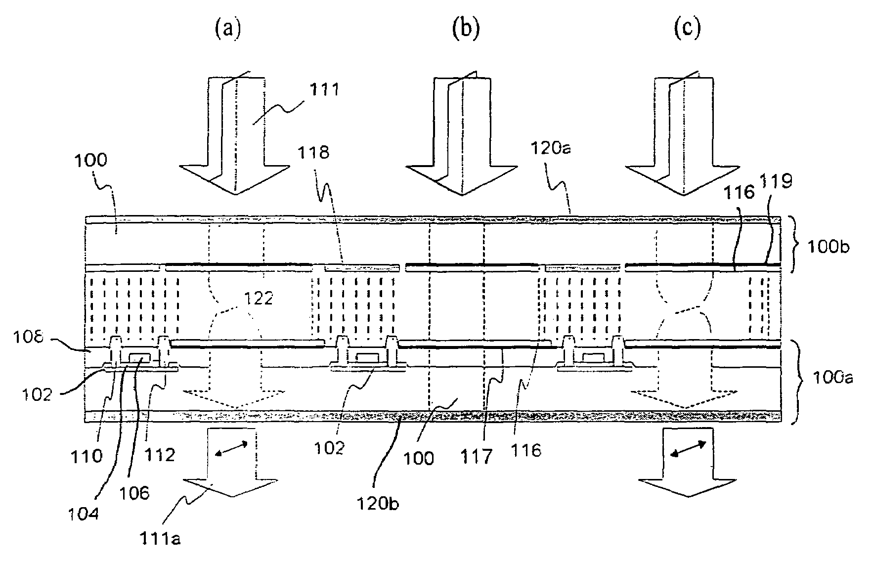
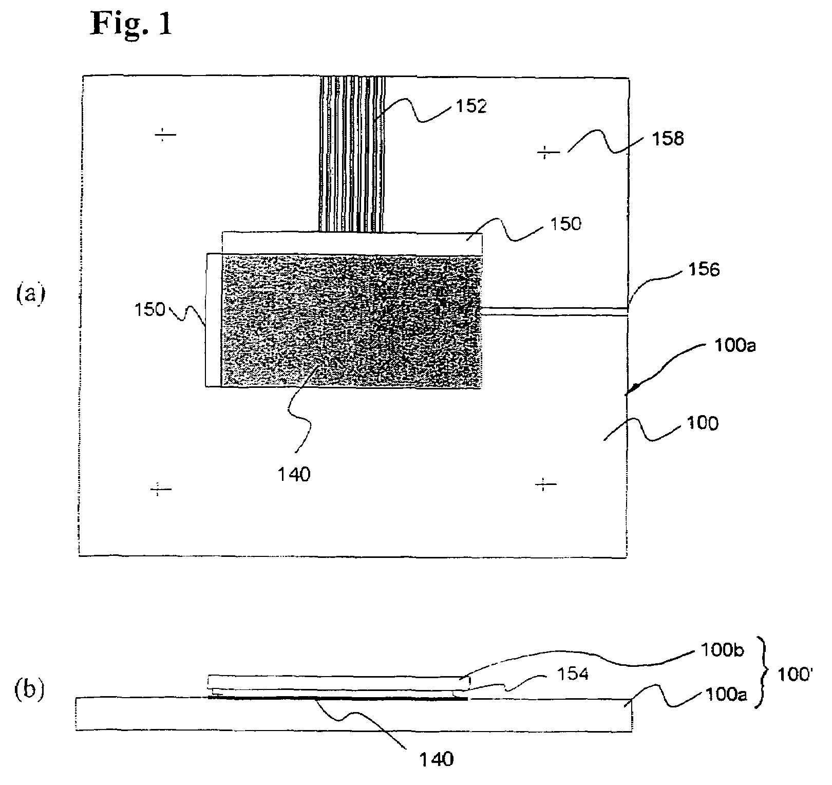
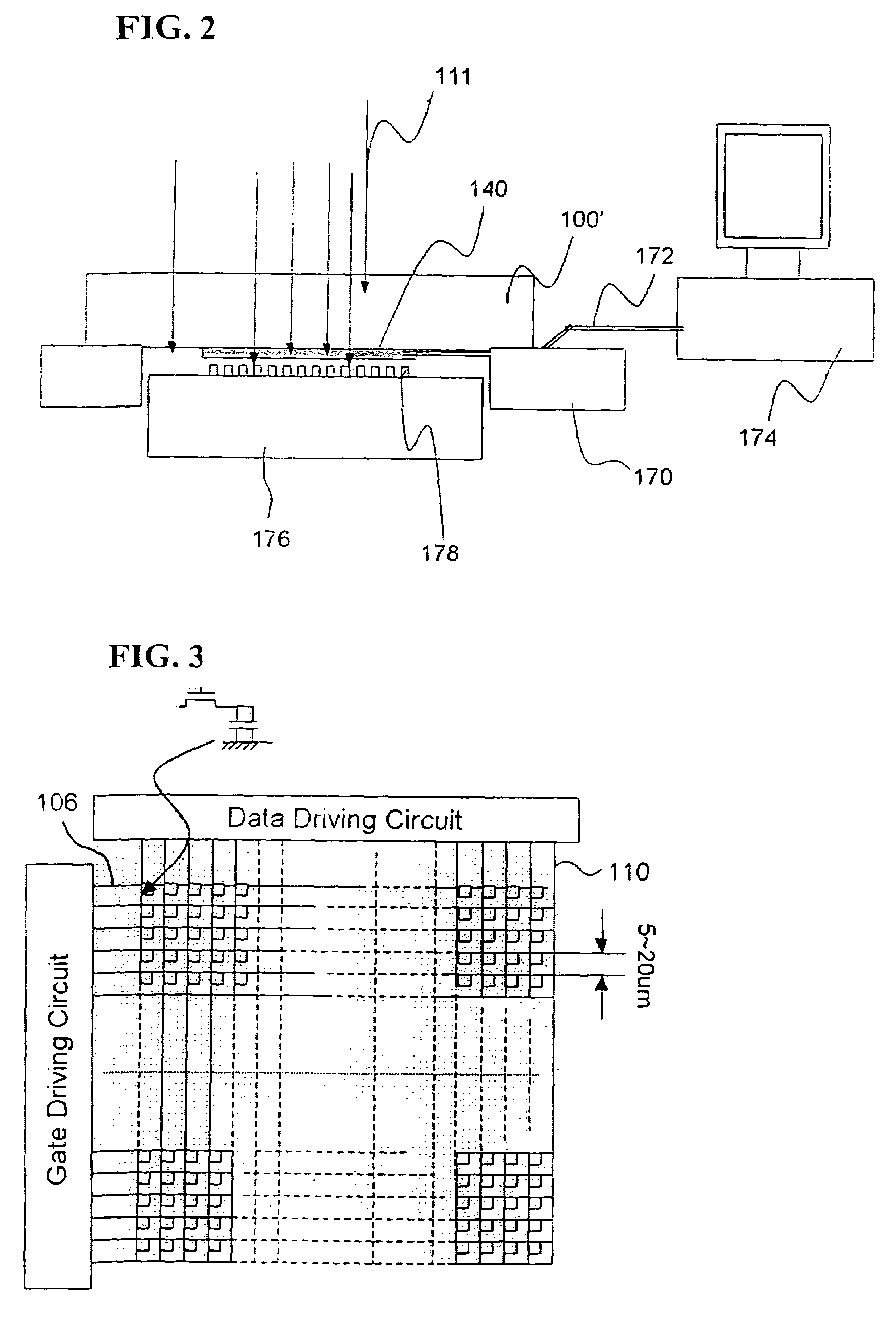
[0035]Next, the structure of a LCD type programmable mask for switching the ultraviolet light and a method for manufacturing the same will be described. The structure of the LCD type programmable mask is schematically described with reference to the accompanying drawings, and a circuit diagram of the programmable mask, a sectional view of the programmable mask, the operation of the optical valve liquid crystal, and light intensity adjustment and wavelength filter function and non-polarization of the light passing through the programmable mask are desc...


PUM

PropertyMeasurementUnit
wavelengthaaaaaaaaaa
thicknessaaaaaaaaaa
thicknessaaaaaaaaaa

Abstract

A programmable mask used in a photolithography process for fabricating a biomolecule array and a method for fabricating a biomolecule array using the same are disclosed. Particularly, a TFT-LCD type programmable mask for selectively transmitting incident light in accordance with an electrical signal applied thereto and a method for fabricating a biomolecule array using the same are provided. The ultraviolet light is selectively illuminated to a sample substrate so that the biomolecule array having high density can be fabricated.

Description

[0001]The present patent application is a Divisional of application Ser. No. 10 / 246,593, filed Sep. 18, 2002 now abandoned.BACKGROUND OF THE INVENTION[0002]1. Field of the Invention[0003]The present invention relates to a programmable mask adapted for fabricating a biomolecule array and a method for fabricating a biomolecule array using the same, more particularly, to a programmable mask adapted for fabricating the biomolecule array such as DNA by illuminating ultraviolet light to a specific cell and a method for fabricating a biomolecule array using the same.[0004]2. Description of the Prior Art[0005]First, in a biomolecule or a macromolecule array formed on a substrate, the area composed of a kind of the biomolecule or the macromolecule is referred as a cell.[0006]The research for the operation for performing the plurality of experiment at once by using the biomolecule or macromolecule array has been progressed. As the biomolecule or macromolecule array, there are, for example, po...

Claims


Application Information

Patent Timeline
Patent Type & Authority Patents(United States)
IPC IPC(8): G02F1/13C12Q1/68B01J19/00C40B40/06C40B60/14G02F1/1335G02F1/1362G02F1/139G02F1/21G03F7/20
CPCB01J19/0046B82Y30/00G02F1/216G03F7/70291G03F7/7035B01J2219/00434B01J2219/00527B01J2219/00529B01J2219/00596B01J2219/00605B01J2219/00608B01J2219/00659B01J2219/00675B01J2219/00677B01J2219/00689B01J2219/00711B01J2219/00722C40B40/06C40B60/14G02F1/133528G02F1/13454G02F1/13725G02F2203/12H01L27/146C12Q1/68
Inventor JUNG, MOON YOUNYANG, HAE SIKJUN, CHI HOONKIM, YUN TAEKIM, YOUNG SHINSHIN, DONG HO
Owner ELECTRONICS & TELECOMM RES INST
Why Eureka
Try Eureka