Electrode material for lithium secondary battery, electrode structure comprising the electrode material and secondary battery comprising the electrode structure

a lithium secondary battery and electrode structure technology, applied in the manufacture of final products, non-metal conductors, cell components, etc., can solve the problems of high energy-density secondary batteries comparable with lithium primary batteries, difficult to newly construct thermal power plants, and material has not been realized, and achieves high electrical conductivity. , the effect of high electrical conductivity

Inactive Publication Date: 2008-05-27
CANON KK
View PDF20 Cites 57 Cited by
  • Summary
  • Abstract
  • Description
  • Claims
  • Application Information

AI Technical Summary

Benefits of technology

[0084]The lithium secondary battery that uses an electrode structure comprising an electrode material of the present invention as the negative electrode has a high charging / discharging efficiency and capacity and a high energy density owing to the above-mentioned advantageous effects of the negative electrode.
[0085]Herein, the positive electrode 203, which is the counter electrode of the lithium secondary battery using the electrode structure of the present invention as the negative electrode, comprises a positive electrode material that is at least a lithium ion source and serves as a host material for lithium ions, and preferably comprises a layer formed of a positive electrode material that serves as a host material for lithium ions and a current collector. Further, it is preferable that the layer formed of the positive electrode material comprises the positive electrode material that serves as a host material for lithium ions and a binder, and a conductive auxiliary material as occasion demands.
[0086]As the positive electrode material that is a lithium ion source and serves as a host material used in the lithium secondary battery of the present invention, there are preferably included lithium-transition metal oxides, lithium-transition metal sulfides, lithium-transition metal nitrides and lithium-transition metal phosphates. The transition metal for the transition metal oxides, transition metal sulfides, transition metal nitrides or transition metal phosphates includes, for example, metal elements having a d-shell or f-shell, i.e., Sc, Y, lanthanoids, actinoids, Ti, Zr, Hf, V, Nb, Ta, Cr, Mo, W, Mn, Tc, Re, Fe, Ru, Os, Co, Rh, Ir, Ni, Pb, Pt, Cu, Ag, and Au, and in particular Co, Ni, Mn, Fe, Cr, and Ti are preferably used.
[0087]Where the above positive electrode active material is a powder, the positive electrode is made by using a binder, or made by forming the positive electrode active material layer on the current collector by calcination or deposition. Further, when the conductivity of the powder of the positive electrode active material is low, it becomes necessary to suitably mix a conductive auxiliary material therewith as in the above-mentioned formation of the active material layer for the electrode structure. The conductive auxiliary materials and binders that may be used are the same as those mentioned above for the electrode structure 102 of the present invention.
[0088]The current collector material used for the positive electrode is preferably a material that has a high electrical conductivity and is inert to the battery reaction, such as aluminium, titanium, nickel and platinum. Specifically, nickel, stainless steel, titanium and aluminium are preferable, of which aluminium is more preferable because it is inexpensive and has a high electrical conductivity. Further, while the shape of the current collector is a plate shape, this “plate shape” is, within the scope of practical use, not particularly limited in thickness, and encompasses the so-called “foil” shape having a thickness of about 100 μm or less. As the plate shape member, for example, a meshy, spongy or fibrous member, punching metal, or expanded metal can also be employed
[0089]In addition, as the ionic conductor 202 of the lithium secondary battery of the present invention, lithium ion conductors such as a separator holding an electrolyte solution (electrolyte solution prepared by dissolving an electrolyte in a solvent), a solid electrolyte, or a solidified electrolyte obtained by gelling an electrolyte solution with a polymer gel, a complex of a polymer gel and a solid electrolyte can be used. Here, the conductivity of the ionic conductor 202 at 25° C. is preferably 1×10⁻³ S / cm or more, and more preferably 5×10⁻³ S / cm or more.

Problems solved by technology

Thermal power plants use fossil fuels to convert a thermal energy into an electric energy, however they exhaust a large amount of CO2 gas, thereby making it difficult to newly construct thermal power plants.
However, with this “lithium ion battery”, because the negative electrode formed of a carbonaceous material can theoretically intercalate only a maximum of ⅙ of a lithium atom per one carbon atom, a high energy-density secondary battery comparable with a lithium primary battery when using metallic lithium as a negative electrode material has not been realized.
If an amount of lithium more than the theoretical amount is tried to be intercalated in a negative electrode comprising carbon of a “lithium ion battery” during charging or charging is performed under a high current density condition, there is a possibility that lithium metal may grow in a dendrite shape on the carbon negative electrode surface, resulting in an internal short-circuit between the negative and the positive electrodes due to repeated charge / discharge cycles, so that any “lithium ion battery” which has a capacity more than the theoretical capacity of a graphite negative electrode has not provided a sufficient cycle life.
On the other hand, a high-capacity lithium secondary battery that uses metal lithium for a negative electrode has been drawing attention but not put in practical use yet.
This is because the charge / discharge cycle life is very short.
This short charge / discharge cycle life is considered to be ascribed to the fact that metal lithium reacts with impurities such as water or organic solvents contained in the electrolyte to form an insulating film or that the surface of a metallic lithium foil is not flat and has a portion at which an electric field is concentrated, whereby repeated charging / discharging causes lithium to grow in a dendrite shape, resulting in an internal short-circuit between the negative and positive electrodes, thereby leading to the end of the battery life.
However, this method is not currently in wide practical use because the lithium alloy is too hard to wind in a spiral form, and therefore a spiral-wound type cylindrical battery cannot be made, because the cycle life is not sufficiently long, and because an energy density comparable to that of a battery using metal lithium for a negative electrode cannot sufficiently be obtained.
However, in the lithium secondary batteries according to the above-mentioned proposals, the efficiency of the electricity amount involved in lithium release relative to the electricity amount involved in a first lithium insertion does not reach the same level of performance as a graphite negative electrode, so that further improvement in the efficiency have been expected.
However, with this lithium secondary battery, while the theoretical charge capacity calculated for Li4.4Si as a silicon / lithium compound is 4200 mAh / g, an electrode performance allowing lithium insertion / release of an electricity amount exceeding 1000 mAh / g has not been attained, so that development of a high-capacity, long life negative electrode has been desired.

Method used


Image

  • Electrode material for lithium secondary battery, electrode structure comprising the electrode material and secondary battery comprising the electrode structure
  • Electrode material for lithium secondary battery, electrode structure comprising the electrode material and secondary battery comprising the electrode structure
  • Electrode material for lithium secondary battery, electrode structure comprising the electrode material and secondary battery comprising the electrode structure

Examples


example 1

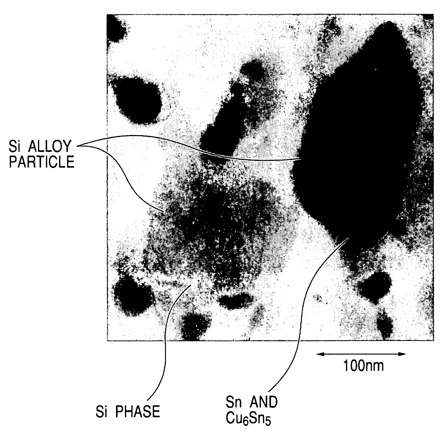
[0114]65% by weight of Si, 30% by weight of Sn and 5% by weight of Cu were melted and mixed to make an alloy, which was subjected to water atomization to prepared a Si—Sn—Cu alloy powder having an average particle diameter of 10 μm. Next, the prepared alloy-powder was ground with a bead mill (ball mill using beads with comparatively small diameter as grinding media) to obtain a Si—Sn—Cu alloy fine powder. This grinding was performed using zirconia beads in isopropyl alcohol.

[0115]Then, processing for 2 hours in a high-energy planetary-type ball mill in an argon gas atmosphere using balls made of silicon nitride provided an electrode material of Si—Sn—Cu alloy fine powder.

example 2

[0116]An electrode material of a Si—Zn—Cu alloy fine powder was obtained following the same procedure as Example 1 with the exception that an alloy with a composition of 70% by weight of Si, 25% by weight of Zn and 5% by weight of Cu was prepared by a gas atomization process using nitrogen gas.

example 3

[0117]An electrode material of a Si—Sn—Co alloy fine powder was obtained following the same procedure as Example 1 with the exception that an alloy with a composition of 50% by weight of Si, 40% by weight of Sn and 10% by weight of Co was prepared by a water atomization process.


PUM

PropertyMeasurementUnit
particle diameteraaaaaaaaaa
crystallite sizeaaaaaaaaaa

Abstract

There are provided an electrode material for a lithium secondary battery which comprises alloy particles comprising silicon as a major component and having an average particle diameter of 0.02 μm to 5 μm, wherein the size of a crystallite of the alloy is not less than 2 nm but no more than 500 nm and an intermetallic compound containing at least tin is dispersed in a silicon phase and an electrode material for a lithium secondary battery which comprises alloy particles comprising silicon as a major component and having an average particle diameter of 0.02 μm to 5 μm, wherein the size of a crystallite of the alloy is not less than 2 nm but no more than 500 nm and an at least one intermetallic compound containing at least one element selected from the group consisting of aluminum, zinc, indium, antimony, bismuth and lead is dispersed in a silicon phase. Thereby, an electrode material for a lithium secondary battery, an electrode structure comprising the electrode material and a secondary battery comprising the electrode structure are provided in which a drop in capacity due to repeated charging / discharging is small, and the charge / discharge cycle life is improved.

Description

BACKGROUND OF THE INVENTION[0001]1. Field of the Invention[0002]The present invention relates to an electrode material for a lithium secondary battery that comprises a powder of particles comprising silicon as a major component, an electrode structure comprising the electrode material and a secondary battery comprising the electrode structure.[0003]2. Related Background Art[0004]Recently, it has been said that because the amount of CO2 gas contained in the air is increasing, global warming may be occurring due to the greenhouse effect. Thermal power plants use fossil fuels to convert a thermal energy into an electric energy, however they exhaust a large amount of CO2 gas, thereby making it difficult to newly construct thermal power plants. Accordingly, for effective use of an electric power generated in thermal power plants, the so-called load leveling approach has been proposed wherein an electric power generated at night, which is an excess power, may be stored in a household seco...

Claims


Application Information

Patent Timeline
Patent Type & Authority Patents(United States)
IPC IPC(8): H01B1/04H01M4/134H01M4/1395H01M4/36H01M4/38H01M4/40H01M4/62H01M10/0525H01M10/36
CPCH01M4/134H01M4/1395H01M4/38Y02E60/122H01M4/405H01M10/0525H01M4/386Y02E60/10Y02P70/50
Inventor ASAO, MASAYAKAWAKAMI, SOICHIROOGURA, TAKAO
Owner CANON KK
Why Eureka
Try Eureka