

Reflective display based on liquid crystal materials
a liquid crystal material and display technology, applied in the field of high contrast displays, can solve the problems of loss of performance, change in reflected color, and harmful uv radiation to liquid crystals, and achieve the effect of reducing eyestrain and pleasing appearan
- Summary
- Abstract
- Description
- Claims
- Application Information
AI Technical Summary
Benefits of technology
Problems solved by technology
Method used
Image

Examples
example 1
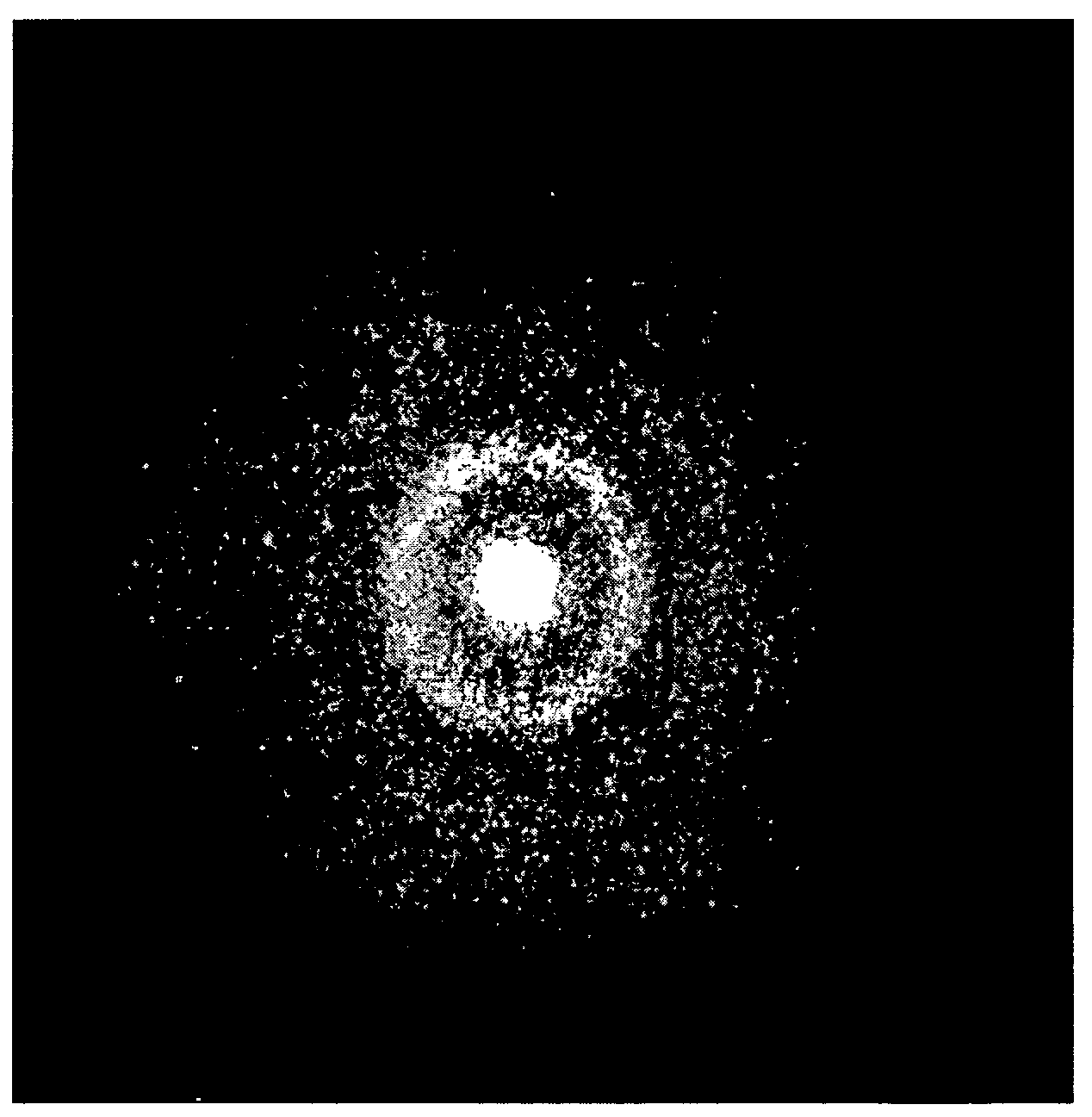
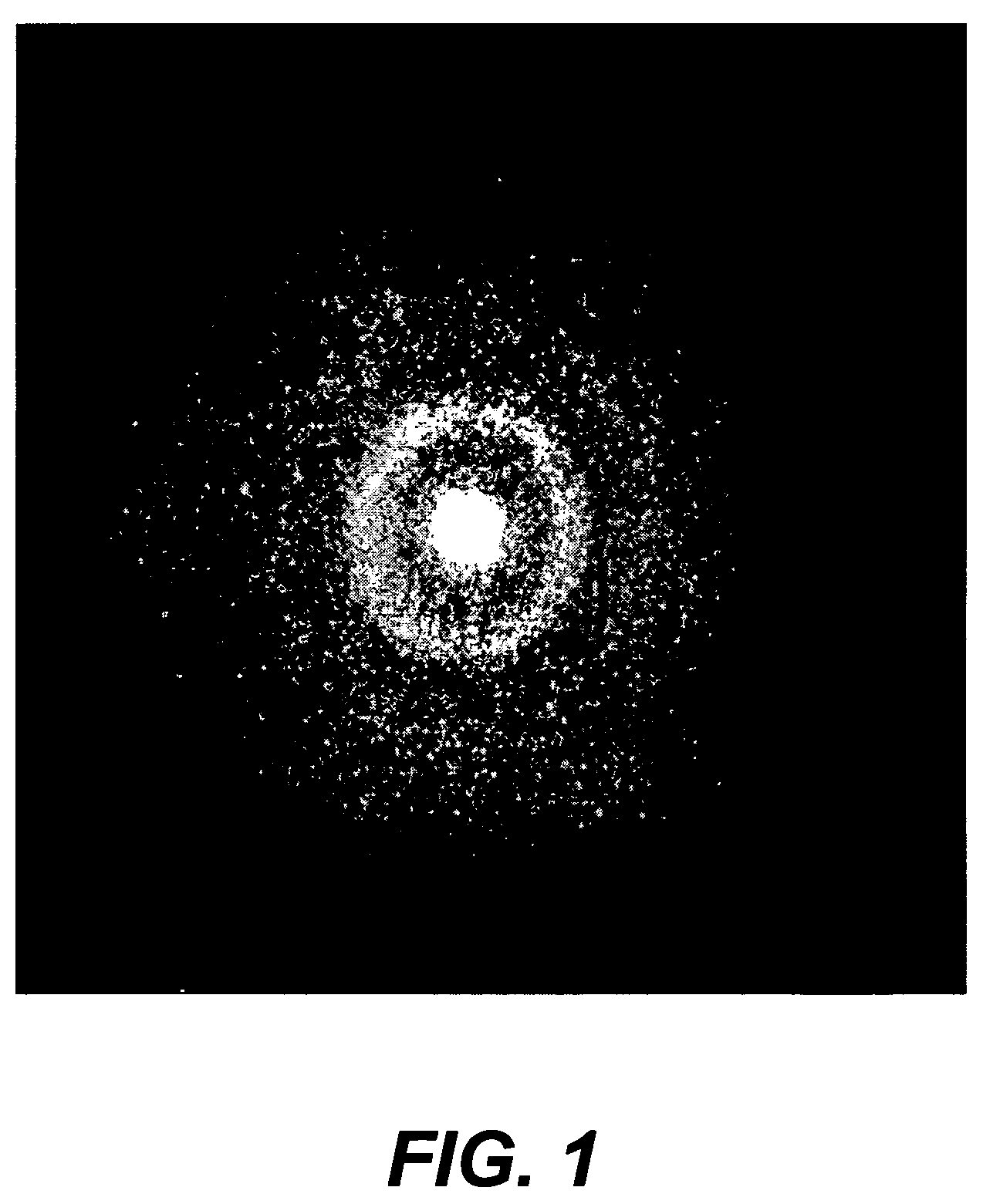
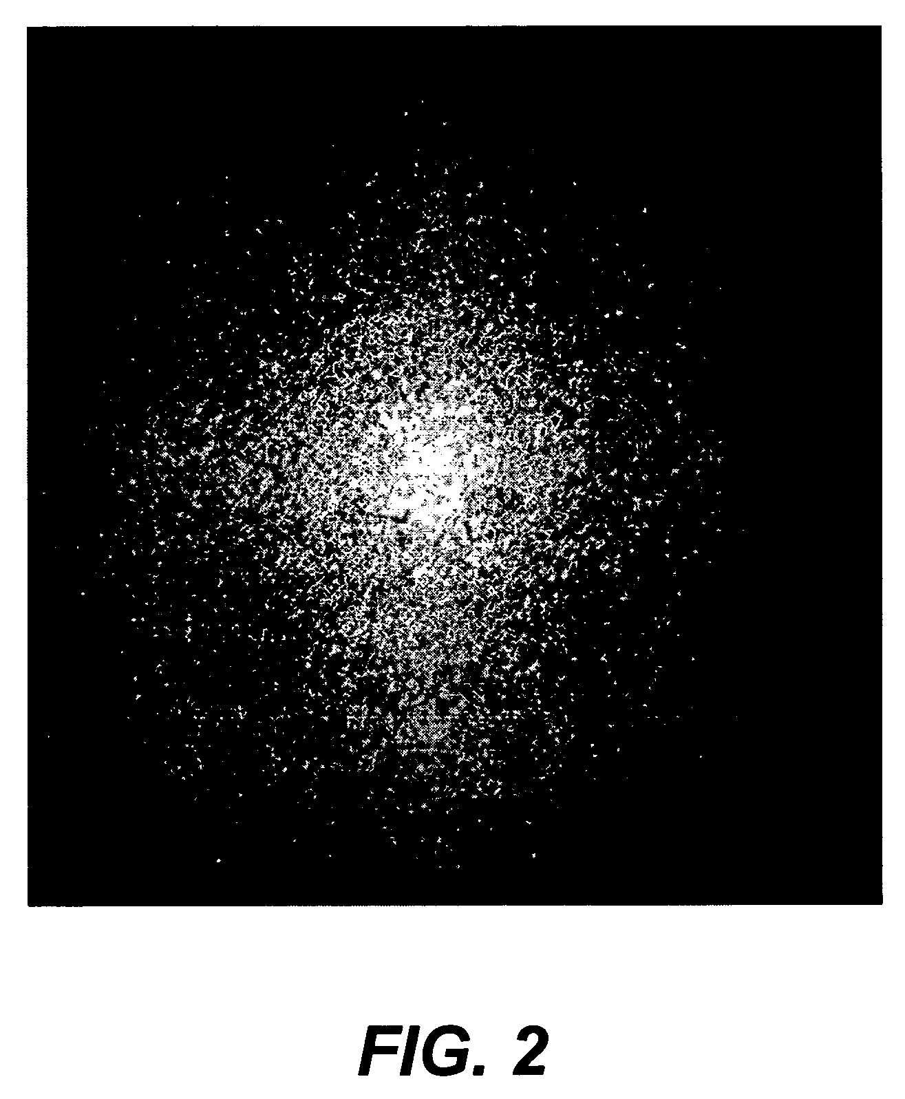
[0118]This example illustrates the close-packed ordered monolayer structure obtained according to the invention compared to the random structure of a control coating.
[0119]Chiral nematic liquid crystal (CLC) compositions with center wavelengths of reflection (CWR) at 540 nm and 590 nm were prepared by adding the appropriate amount of a high twist chiral dopant to the nematic host mixture BL087 obtained from Merck, Darmstadt, Germany. The CLC composition with CWR at 590 nm also contained 0.2% weight / weight (w / w) of the blue absorbing dye Neopen Yellow 057 from BASF Corporation.
Method I (Invention)
[0120]A dispersion of the CLC composition with CWR at 590 nm was prepared as follows. To 241 grams of distilled water was added 3.6 grams of Ludox™ colloidal silica suspension and 7.4 grams of a 10% w / w aqueous solution of a copolymer of methylaminoethanol and adipic acid. To this was added 108 grams of the CLC composition. The mixture was stirred using a Silverson mixer at 5000 rpm. It was ...
example 2
[0126]This example illustrates the improved electro-optical properties of a device fabricated according to the invention compared to a control device.
Method I (Invention)
[0127]A dispersion of CLC material was prepared in a manner similar to Method I of Example 1.
[0128]The dispersion was mixed with an aqueous solution of Type IV cattle gelatin having a weight-average molecular weight of 117,000 and a polydispersity of 3.7, an aqueous solution of polyvinylalcohol (PVA)(type GL-05 from Nippon Gohsei Limited), a solution of Aerosol OT in water and a solution bis(vinylsulfonyl)methane in water to give a coating composition containing 15% w / w CLC material, 4.5% gelatin, 0.5% PVA, 0.07% Aerosol OT and 0.1% bis(vinylsulfonyl)methane. The composition was spread over a plastic support with a thin layer of indium tin oxide (ITO) to give a uniform coverage of about 5400 mg / m2 of CLC material. The coated layer was referred to as layer 1. During the operation, the plastic support was placed over ...
example 3
Invention
[0134]A dispersion of CLC material and coating composition were prepared as described under Method 1 of Example 1. The composition was spread over a plastic support (Dupont ST504) with a thin layer of ITO (approximately 240 Angstroms in thickness and 300 ohm / sq resistivity) at 37.7 cm3 / m2 to give a uniform dry coverage of about 5400 mg / m2 for the CLC material. During the operation, the plastic support was placed over a coating block that was maintained at 45 C and the coating composition was delivered at 23 C. The resulting coating of the imaging layer was dried at 45 C. All of these temperatures were above the sol-gel transition temperature of the binder.
[0135]The coating of the imaging layer was kept aside for 48 h to allow the cross-linking of gelatin to go to completion. The coating was then placed on a coating block that was maintained at 30 C. A composition containing 4% Type IV cattle gelatin, 1.4% carbon black and 0.1% Aerosol OT in distilled water was then spread o...
PUM
| Property | Measurement | Unit |
|---|---|---|
| chill set temperature | aaaaa | aaaaa |
| chill set temperature | aaaaa | aaaaa |
| RMS surface roughness | aaaaa | aaaaa |
Abstract
Description
Claims
Application Information