Control system for internal combustion engine

a control system and internal combustion engine technology, applied in the direction of electrical control, process and machine control, instruments, etc., can solve the problems of difficult control of intake air amount, difficult to obtain the required performance using the conventional control method which supplies an excessive amount of air, etc., and achieve good operating performance and exhaust characteristics.

Inactive Publication Date: 2008-07-15
HONDA MOTOR CO LTD
View PDF14 Cites 83 Cited by
  • Summary
  • Abstract
  • Description
  • Claims
  • Application Information

AI Technical Summary

Benefits of technology

[0007]An aspect of the present invention is to provide a control system for an internal combustion engine, which more strictly controls the intake gas state and the air-fuel ratio of an air-fuel mixture in an internal combustion engine, wherein good operating performance and exhaust characteristics are obtained.
[0009]With the above-described structural configuration, the intake gas state parameters indicative of the state of the intake gases supplied to the engine are detected, and the demand values of the intake gas state parameters are calculated according to the operating condition parameters indicative of the operating condition of the engine. Further, the intake gas state is controlled so that the intake gas state parameters coincide with the demand values, and the fuel injection amount is controlled according to the operating condition parameters and the deviations of the intake gas state parameters from the demand values. Therefore, the desired intake gas state according to the engine operating condition is realized, and the control of the fuel injection amount suitable for the intake gas state is performed, wherein good engine operating performance and exhaust characteristics are obtained.
[0015]By using the above-listed intake gas state parameters, it is possible to control an amount of masses of oxygen and inert gases (gases other than oxygen) in the combustion chamber to the desired values, thereby performing appropriate and accurate fuel injection control.
[0017]With the above-described structural configuration, the intake gas state parameters further include the intake gas temperature. Therefore, the fuel injection control is performed in view of any influence from changes in the intake gas temperature, thereby improving accuracy of the fuel injection control.

Problems solved by technology

Accordingly, it is extremely difficult to obtain the required performance using the conventional control method which supplies an excessive amount of air compared to the fuel supply amount.
Consequently, according to the conventional control system, in recent years it has been difficult to perform the intake air amount control and the fuel supply control which satisfy a strict demand of the engine performance.

Method used


Image

  • Control system for internal combustion engine
  • Control system for internal combustion engine
  • Control system for internal combustion engine

Examples


first embodiment

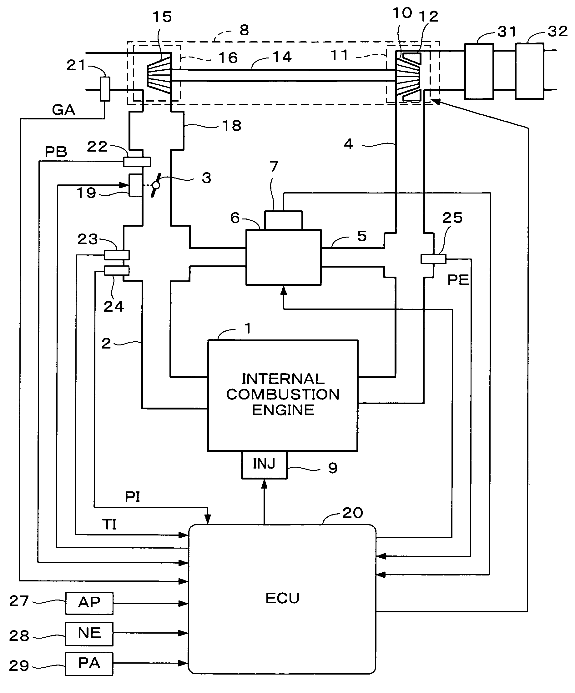
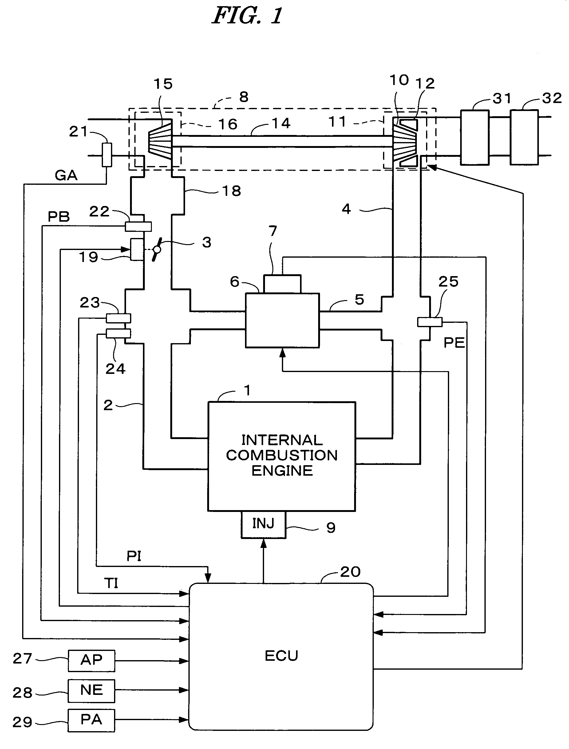
[0049]FIG. 1 is a schematic diagram showing a configuration of an internal combustion engine and a control system therefore according to a first embodiment of the present invention. The internal combustion engine 1 (hereinafter referred to as “engine”) is a diesel engine wherein fuel is injected directly into the cylinders. Each cylinder is provided with a fuel injection valve 9 electrically connected to an electronic control unit 20 (hereinafter referred to as “ECU”). The ECU 20 controls a valve opening timing and a valve opening period of each fuel injection valve 9.

[0050]The engine 1 has an intake pipe 2, an exhaust pipe 4, and a turbocharger 8. The turbocharger 8 includes a turbine 11 and a compressor 16. The turbine 11 has a turbine wheel 10 rotatably driven by the kinetic energy of exhaust gases. The compressor 16 has a compressor wheel 15 connected to a turbine wheel 10 by a shaft 14. The compressor wheel 15 pressurizes (compresses) the intake air of the engine 1.

[0051]The tu...

second embodiment

[0200]In this embodiment, the demand fresh air flow rate Giades, the demand intake pressure Pides, and a demand intake oxygen partial pressure Piodes are calculated according to the engine rotational speed NE and the demand torque TRQ. Also, intake gas state control is performed to realize the demand intake pressure Pides and the demand intake oxygen partial pressure Piodes. Further, the fuel injection control corresponding to the demand intake pressure Pides and the demand intake oxygen partial pressure Piodes is performed. The demand intake oxygen partial pressure Piodes is a demand value of a partial pressure of oxygen in the intake gases (hereinafter referred to as “intake oxygen partial pressure”). In this embodiment, the demand fresh air flow rate Giades is applied only to the calculation of the target power Wcref of the compressor wheel 15 in the intake gas state control block, i.e., the demand fresh air flow rate Giades does not correspond to the “intake gas state parameter”...


PUM


Abstract

A control system for an internal combustion engine having at least one fuel injection valve for injecting fuel to an intake pipe or a combustion chamber of the engine. Intake gas state parameters indicative of a state of the intake gases supplied to the engine are detected. Demand values of the intake gas state parameters are calculated according to operating condition parameters indicative of an operating condition of the engine. The intake gas state is controlled so that the intake gas state parameters coincide with the demand values. A control value is then calculated according to the operating condition parameters and deviations of the intake gas state parameters from the demand values. Accordingly, an amount of fuel injected by the at least one fuel injection valve is controlled according to the control value.

Description

BACKGROUND OF THE INVENTION[0001]1. Field of the Invention[0002]The present invention relates to a control system for an internal combustion engine and, particularly, to a control system that accurately controls an air-fuel ratio in a combustion chamber of the internal combustion engine having an exhaust gas recirculation mechanism.[0003]2. Description of the Related Art[0004]Japanese Patent Laid-open No. H08-61112 discloses a control system for a diesel engine having an exhaust gas recirculation mechanism. According to the disclosed control system, a gas amount Gf supplied to a combustion chamber is calculated using a map which is set according to a depressed amount of an accelerator and an engine rotational speed, and an intake air amount Ga is detected by an intake air amount sensor. Further, the intake air amount Ga is subtracted from the gas amount Gf to calculate a recirculated gas flow rate Ge. An air amount Gae in exhaust gases recirculated through the exhaust gas recirculat...

Claims


Application Information

Patent Timeline
Patent Type & Authority Patents(United States)
IPC IPC(8): G06F19/00F02D11/10F02D21/08F02D41/02F02D41/04F02D45/00
CPCF02D41/0002F02D41/32F02D41/0007F02D41/0072F02D41/1401F02D41/3064Y02T10/42F02D2041/1433F02D2200/0402F02D2200/0406F02D2200/0414F02D41/38Y02T10/40
Inventor UENO, MASAKIWADA, KATSUJI
Owner HONDA MOTOR CO LTD
Why Eureka
Try Eureka