
Process and apparatus for treating a workpiece with gases

a technology for treating workpieces and workpieces, applied in the direction of sustainable manufacturing/processing, cleaning using liquids, final product manufacturing, etc., can solve the problems of high cost of process chemicals, so as to reduce the required process time, increase the amount of gas available, and increase the reaction rate

Inactive Publication Date: 2008-08-26
OEM GRP LLC
View PDF156 Cites 15 Cited by
  • Summary
  • Abstract
  • Description
  • Claims
  • Application Information

AI Technical Summary

Benefits of technology

[0008]For many years, wafers were cleaned in typically three or four separate steps using strong acids, such as sulfuric acid, and using strong caustic solutions, such as mixtures of hydrogen peroxide or ammonium hydroxide. Organic solvents have also been used with wafers having metal films. While these methods performed well, they had certain disadvantages, including the high cost of the process chemicals, the relatively long time required to get wafers through the various cleaning steps, high consumption of water due to the need for extensive rinsing between chemical steps, and high disposal costs. As a result, extensive research and development efforts focused on finding better wafer cleaning techniques.
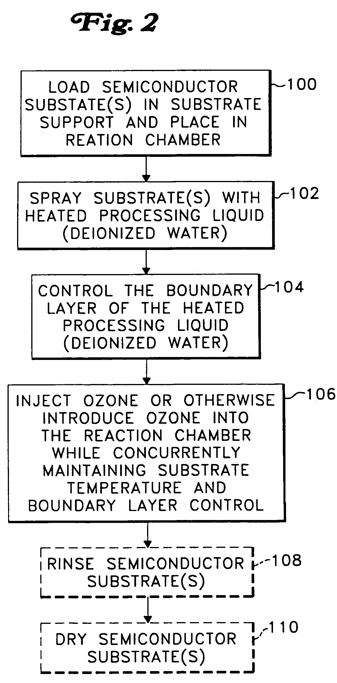
[0009]More recently, the semiconductor manufacturing industry began to acknowledge a revolutionary new process for cleaning wafers, using ozone diffused through a thin layer of heated water on the wafers. This ozone diffusion process has proven itself to be highly effective in cleaning contamination and organic films off of wafers, while avoiding many of the disadvantages of the older methods using acids and caustics. The advantages of the ozone diffusion process are that is it fast, requires no expensive and toxic liquid acids or caustics, and operates effectively as a spray process, which greatly reduces water consumption and space requirements.
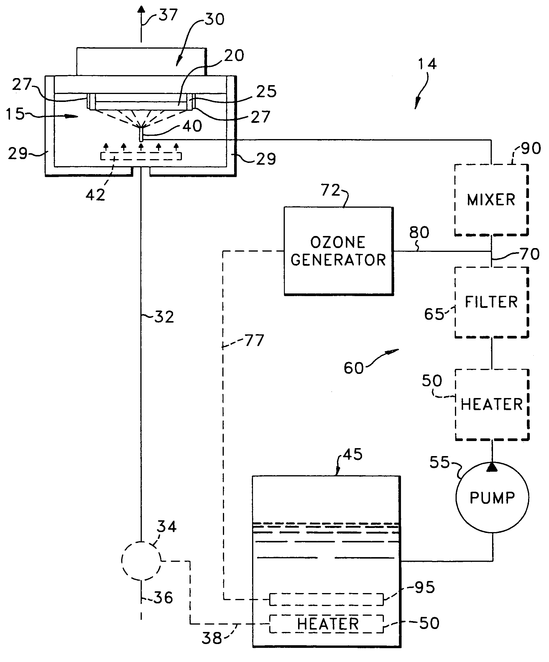
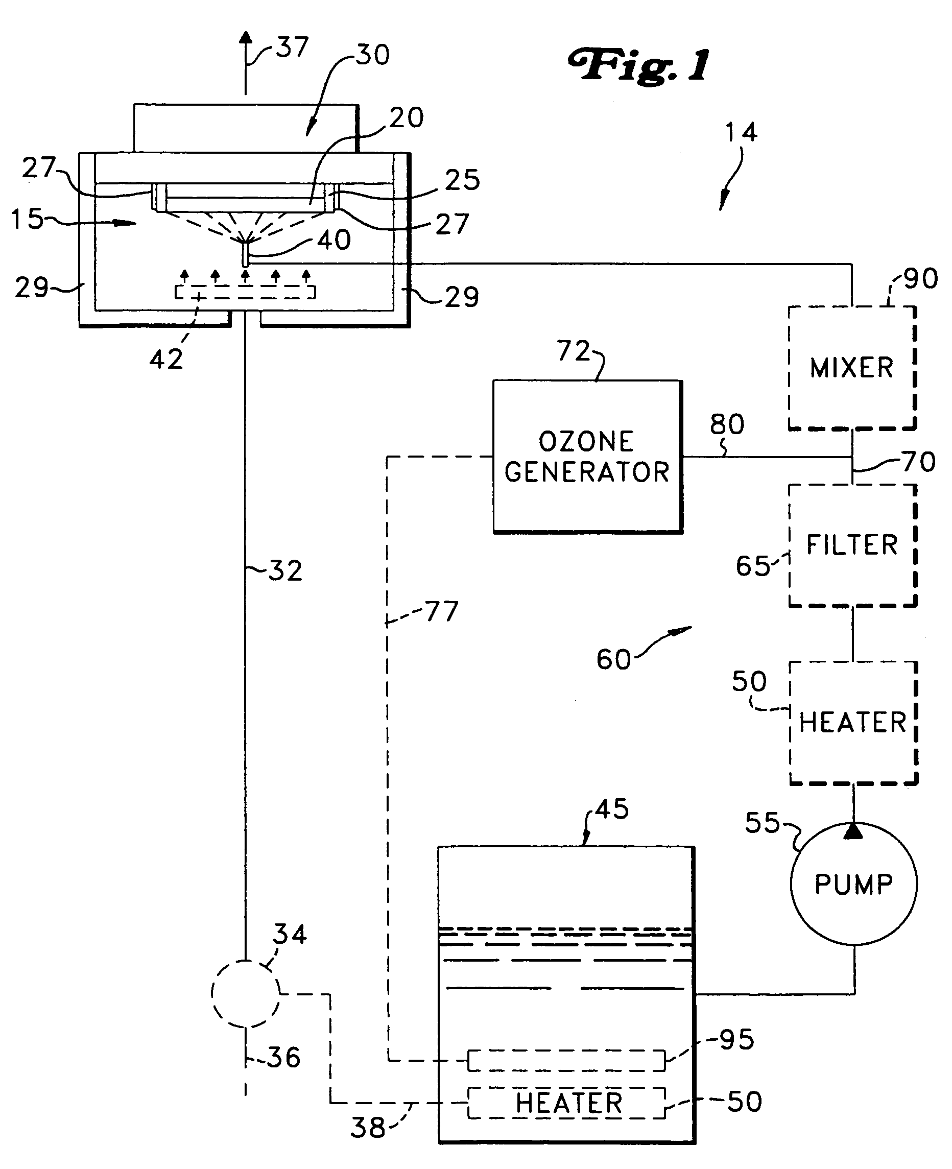
[0011]A workpiece is cleaned or processed via a gas, such as ozone, which chemically reacts with contaminants on the workpiece surface. The gas is brought into contact with the workpiece surface via bulk transport, by entraining the gas into a stream, spray or jet of liquid directed at the wafer surface. A layer of liquid is advantageously formed on the wafer surface. Gas introduced into the chamber or space around the workpiece diffuses through the layer of liquid and chemically reacts with contaminants on the workpiece surface. Use of entrainment and diffusion together increases the amount of gas available for reaction at the workpiece surface, increases the reaction rate, and decreases required process times. With this method, the amount of gas needed for processing is also reduced.
[0012]Ozone (or other process gas) may be entrained in the liquid by injecting the ozone into the liquid, and then subsequently spraying the liquid out of a spray nozzle. Alternatively, entrainment may be achieved by introducing ozone into the liquid after the liquid emerges from a spray nozzle, or other outlet. Nozzles using sonic energy may be used. The liquid is advantageously heated, to accelerate the cleaning or processing chemical or oxidizing reactions. The liquid in many applications is water, and may optionally include one or more chemical additives. The workpiece may be rotated during processing, to help uniformly distribute the liquid across the workpiece surface, to maintain a liquid layer of desired thickness on the workpiece surface, and / or to maintain a flow of fresh liquid on the workpiece surface. Steam may be used with the liquid, or in place of the liquid.

Problems solved by technology

This makes these microelectronic devices highly susceptible to performance degradation or even complete failure due to contamination by organic or metal particles.
While these methods performed well, they had certain disadvantages, including the high cost of the process chemicals, the relatively long time required to get wafers through the various cleaning steps, high consumption of water due to the need for extensive rinsing between chemical steps, and high disposal costs.

Method used


Image

  • Process and apparatus for treating a workpiece with gases
  • Process and apparatus for treating a workpiece with gases
  • Process and apparatus for treating a workpiece with gases

Examples


Embodiment Construction

[0034]A workpiece is defined here to include any object formed from a substrate upon which microelectronic circuits or components, data storage elements or layers, and / or micro-mechanical or micro-electromechanical elements are or can be formed. The apparatus and methods described here may be used to clean or process workpieces such as semiconductor wafers, silicon wafers, as well as other workpieces such as flat panel displays, hard disk media, CD glass, memory media, MEMs devices, etc., all collectively referred to here as a workpiece.

[0035]Although the systems in FIGS. 1-6 are generally illustrated as single wafer systems, these systems and methods may also be used on a batch processing of workpieces, for example as shown in FIGS. 14 and 15. Turning now to FIG. 1, in a processing or cleaning system 14, a workpiece 20 is preferably supported within a process chamber 15 by a workpiece holder, for example, a rotor assembly 30 having multiple supports 25. The rotor assembly 30 in FIG...


PUM

PropertyMeasurementUnit
temperatureaaaaaaaaaa
volumeaaaaaaaaaa
thicknessaaaaaaaaaa

Abstract

In a method and apparatus for cleaning or processing a workpiece, a process gas is brought into contact with the workpiece by diffusion through a heated liquid layer on the workpiece, and by bulk transport achieved by entraining the gas in a liquid stream, spray or jet impinging on the workpiece. The process gas, which may be ozone, is entrained in the liquid via entrainment nozzles. Use of entrainment and diffusion together increases the amount of gas available for reaction at the workpiece surface, increases the reaction rate, and decreases required process times.

Description

BACKGROUND OF THE INVENTION[0001]This application is a Continuation-in-Part of U.S. patent application Ser. No. 09 / 925,884, filed Aug. 6, 2001 ; which is a Continuation-in-Part of U.S. patent application Ser. No. 09 / 621,028, filed Jul. 21, 2000, and now U.S. Pat. No. 6,869,487; which:[0002]A.] is a Continuation-in-Part of U.S. patent application Ser. No. 08 / 853,649, filed May 9, 1997, now U.S. Pat. No. 6,240,933;[0003]B.] is a Continuation-in-Part of U.S. patent application Ser. No. 09 / 061,318, filed Apr. 16, 1998, now abandoned,[0004]C.] is a Continuation-in-Part of International Application No. PCT / US99 / 08516, filed Apr. 16, 1999, claiming priority to U.S. Provisional Patent Application Ser. No. 60 / 099,067, filed Sep. 3, 1998 and 60 / 125,304, filed Mar. 19, 1999; and[0005]D.] claims priority to U.S. Provisional Patent Application Ser. No. 60 / 145,350, filed Jul. 23, 1999.[0006]This Application also claims priority to U.S. Provisional Patent Application Ser. No. 60 / 486,771, filed Jul...

Claims


Application Information

Patent Timeline
Patent Type & Authority Patents(United States)
IPC IPC(8): B08B3/00B08B3/02B08B3/04B08B3/08B08B7/00H01L21/00H01L21/02H01L21/306H01L23/495H05K3/34
CPCB08B3/00B08B3/02B08B3/044B08B3/08B08B7/00H01L21/02052H01L21/02054H01L21/67017H01L21/6704H01L21/67051H01L23/49582H05K3/3426Y10S134/902B08B2203/005B08B2203/007B08B2203/0288B08B2230/01H01L2924/0002H01L2924/00Y02P70/50
Inventor BERGMAN, ERIC J.
Owner OEM GRP LLC
Learn More