Furnace using plasma ignition system for hydrocarbon combustion

a plasma ignition and hydrocarbon combustion technology, which is applied in the combustion of lump and pulverized fuel, combustion types, lighting and heating apparatuses, etc., can solve the problems of absolutely no fuel treatment capability, 1. less than optimal fuel efficiency, and 2. the combustion process of diesel engines, etc., to achieve greater fuel efficiency, more time for heat transfer, and greater fuel efficiency

Inactive Publication Date: 2008-10-14
JAYNE MICHAEL E
View PDF8 Cites 11 Cited by
  • Summary
  • Abstract
  • Description
  • Claims
  • Application Information

AI Technical Summary

Benefits of technology

[0023]Both the chemistry of the fuel and the combustion process itself are completely changed by the “Plasma ball” point of use fuel treatment method and apparatus when utilized in a hydrocarbon fuel burner. It is believed to act as an electrical catalyst which greatly promotes the immediate and complete combustion of all of the fuel resulting in the following advantageous effects:
[0024]1) Greater fuel efficiency as a result of earlier completion of combustion thus allowing more time for heat transfer from the combustion gases to the heat exchanger wall.
[0025]2) Greater fuel efficiency than available from the present technology oil burners by burning completely those hydrocarbon components usually coming out of the exhaust flue as hydrocarbon emissions such as carbon monoxide, particulate matter, soot, and others.
[0026]3) Reduced hydrocarbon pollutant emissions as a direct result of complete combustion of all of the fuel.
[0027]4) The ability to greatly reduce pollutant emissions of oxides of nitrogen by making possible the much more aggressive utilization of exhaust gas recirculation without the loss of combustion efficiency.
[0028]5) The ability to maintain stable combustion when using fuels contaminated with water.

Problems solved by technology

As described in applicant's prior applications listed above and incorporated herein by reference, there are numerous problems with the combustion process for diesel engines.
Although these oil burner ignition systems are simple, reliable, and cheap they have absolutely no fuel treatment capability.
1. Less than optimal fuel efficiency as a result of incomplete combustion;
2. Pollutant emissions as evidenced by the production of oxides of nitrogen (NOx), carbon monoxide (CO), hydrocarbons, and particulates (soot) that are observed in the exhaust output;
3. Unstable combustion when dealing with fuel that has been contaminated by water; and
4. Imposed limitations on the fuel oil weight used in a given burner design.
None of these approaches has the effect of chemically altering the fuel on its molecular level.

Method used


Image

  • Furnace using plasma ignition system for hydrocarbon combustion
  • Furnace using plasma ignition system for hydrocarbon combustion
  • Furnace using plasma ignition system for hydrocarbon combustion

Examples


Embodiment Construction

[0069]The invention will now be described in further detail in connection with illustrative preferred embodiments for improving combustion in a direct injected internal combustion engine enabling the engine to achieve better fuel economy, reduced pollutant emissions, and more power. Within the scope of the present invention, this system could be applied to gas turbines and to reciprocating internal combustion engines that are direct injected of either the 2-stroke or the 4-stroke type that have been designed for use with any type of combustible fuel including gasoline, diesel or jet fuel.

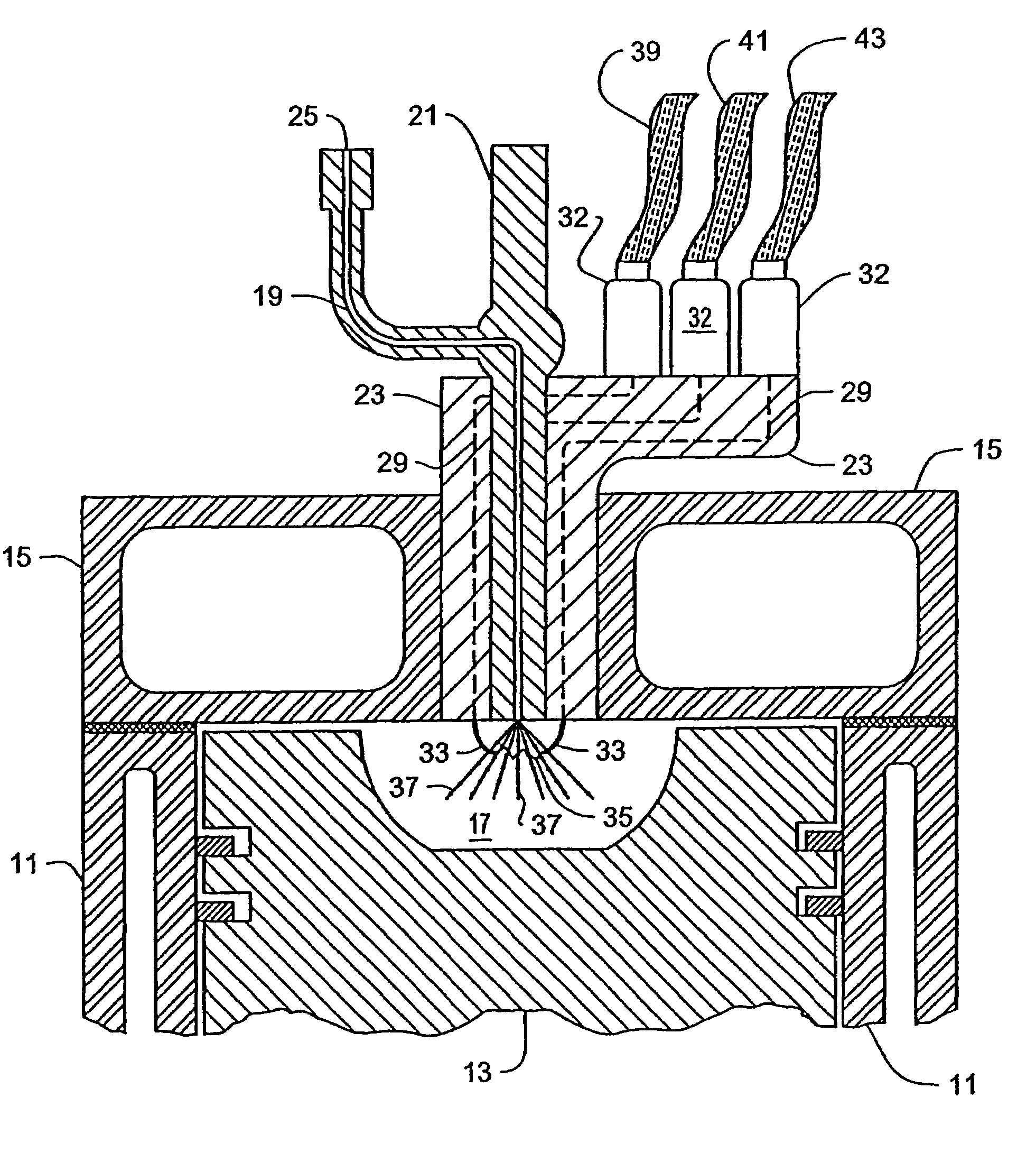
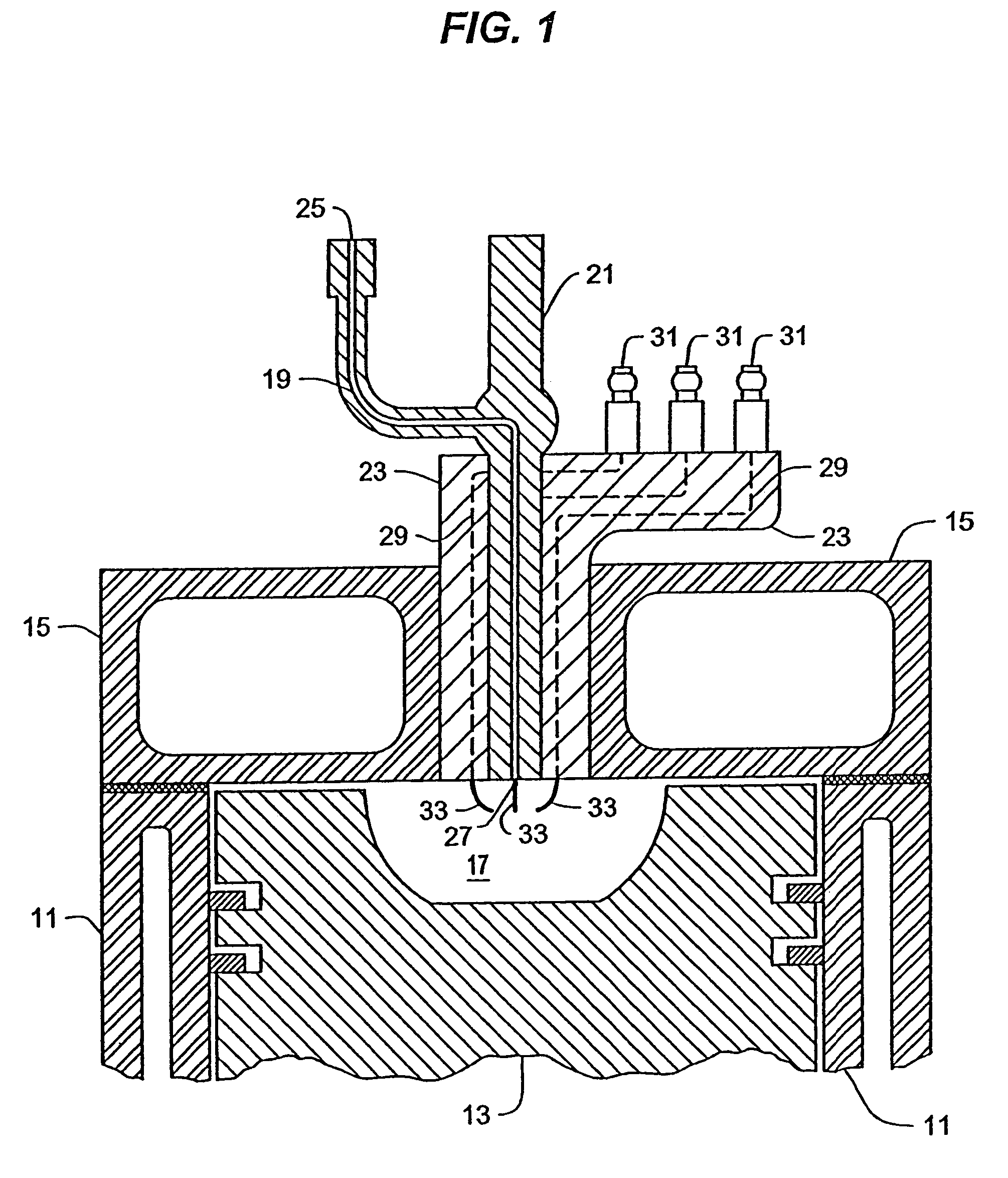
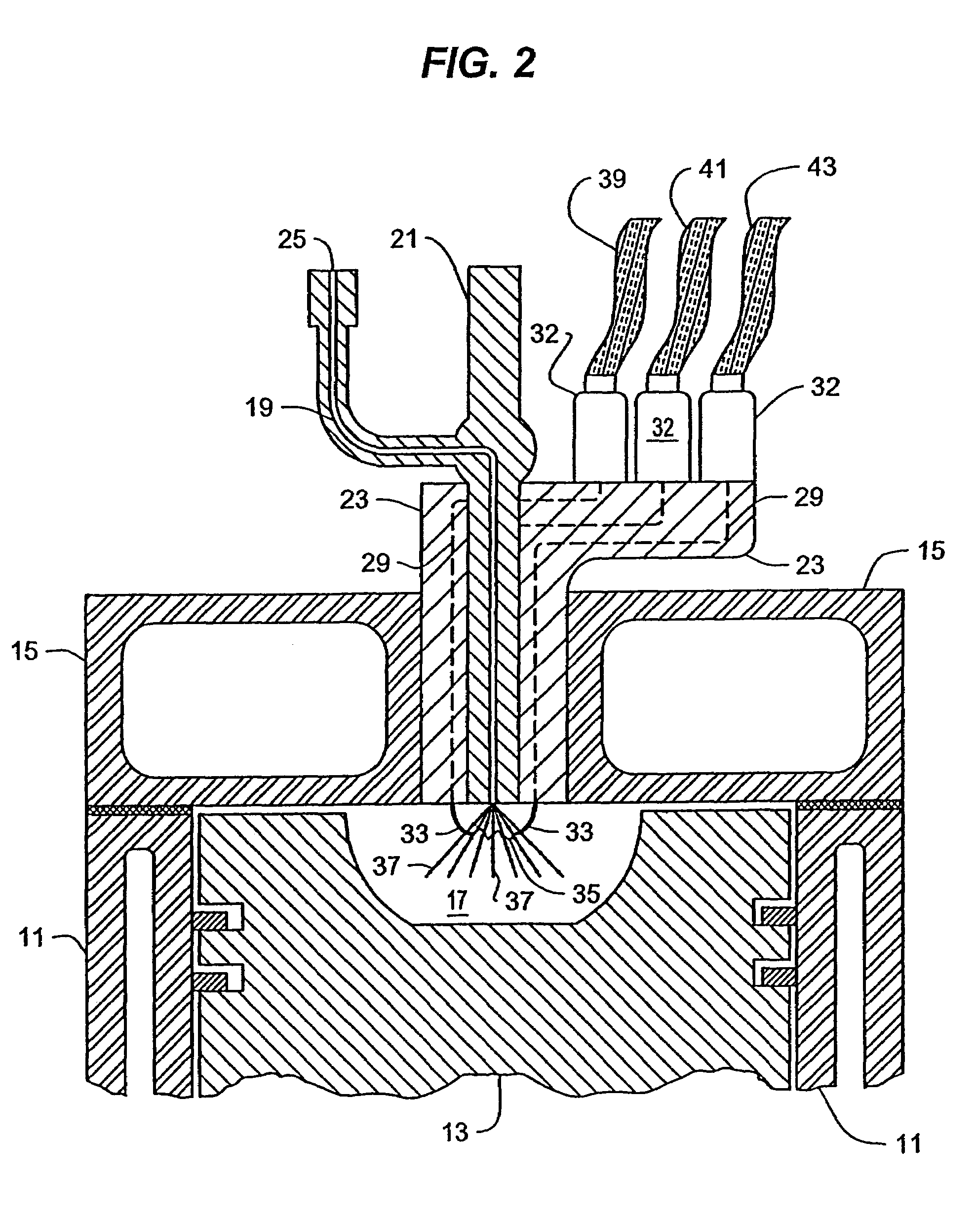
[0070]Referring to FIG. 1, the present invention is shown mounted in a cylinder head 15 of a diesel engine. An engine block 11 has placed inside it a piston 13 and mounted on top of the engine block 11 is the cylinder head 15. A combustion chamber 17 is located inside the area surrounded by the engine block 11, the piston 13, and the cylinder head 15. Passing through the cylinder head 15 is a fuel i...


PUM

PropertyMeasurementUnit
voltageaaaaaaaaaa
areaaaaaaaaaaa
electrical energyaaaaaaaaaa

Abstract

An apparatus and method for the creation, placement and control of an area of electrical ionization within an internal combustion engine combustion chamber or a fuel burner for a furnace is disclosed. A furnace includes a fuel source, a fuel burner, a plasma nozzle and igniter assembly, and the associated housing and flue structures. The plasma nozzle and igniter assembly is arranged so that the fuel sprayed out from the nozzle into the combustion area passes through or in close proximity to the area of plasma ionization. A fuel burner equipped with this electrical ionization device has its fuel efficiency enhanced by the complete and immediate combustion of substantially all of the fuel that passes through the area of plasma ionization. Exhaust gas recirculation using this system is also disclosed.

Description

CROSS REFERENCE TO RELATED APPLICATIONS[0001]This new application is a continuationin-part application of U.S. patent application Ser. No. 10 / 321,721 filed on Dec. 18, 2002, now U.S. Pat. No. 6,883,490, which is a continuation of U.S. application Ser. No. 09 / 954,195 filed on Sep. 18, 2001, now abandoned, which is a continuation of U.S. application Ser. No. 09 / 501,788 filed on Feb. 11, 2000, now U.S. Pat. No. 6,289,868. These prior applications are incorporated herein by reference.BACKGROUND OF THE INVENTION[0002]1. Field of the Invention[0003]The present invention relates to a method and apparatus for improving fuel burners in furnaces by using a plasma ignition system.[0004]2. Description of the Related Art[0005]As described in applicant's prior applications listed above and incorporated herein by reference, there are numerous problems with the combustion process for diesel engines. None of the prior art references disclosed an apparatus that will allow for the initiation of combus...

Claims


Application Information

Patent Timeline
Patent Type & Authority Patents(United States)
IPC IPC(8): B23K10/00F02B23/04F02B23/08F02B23/10F23Q3/00
CPCF02B23/04F02B23/08F02B23/101Y02T10/125Y02T10/12
Inventor JAYNE, MICHAEL E.
Owner JAYNE MICHAEL E
Why Eureka
Try Eureka