Beam neutralization in low-energy high-current ribbon-beam implanters

a ribbon beam and high-current technology, applied in the direction of mechanical equipment, nuclear engineering, machines/engines, etc., can solve the problems of inability to achieve the ion focusing needed for proper operation, the inability to reduce the size of the ribbon beam,

Active Publication Date: 2008-10-21
VARIAN SEMICON EQUIP ASSOC INC
View PDF4 Cites 3 Cited by
  • Summary
  • Abstract
  • Description
  • Claims
  • Application Information

AI Technical Summary

Benefits of technology

[0034]A serious issue that must be addressed when using plasma transport for introducing neutralizing electrons is disposing of the unwanted gas: an inherent part of the plasma generation process. Very high pumping speeds are needed and in conventional pumping geometries the use of turbine pumps or cryogenic pumps are usually conductance limited by the vacuum impedance of the plumbing that couples the pump to the chamber.
[0038]One important issue that is addresses in the present disclosure is a method for moving the electrons through the volume of the ion beam and not allow them to be concentrated near the spot where they are introduced. This necessary motion is achieved by using E×B electron drift around the edges of the magnetic region coupled with B×grad B and curvature drifts. The details of these processes are discussed on pages 23-30 in the book entitled “Plasma Physics and Controlled Fusion” written by F. F. Chen, published by Plenum Press in 1983.

Problems solved by technology

The resulting disruptive effects on ribbon-beam shape are particularly troublesome when ion energies are low and when the charged dopant atoms pass through deflecting magnetic fields.
The resulting beam expansion can cause unacceptable losses of ions to the walls and the impairment of the ion focusing needed for proper operation.
However, it should be emphasized that D.C. ribbon beam technology has special problems of its own particularly during the production of low-energy ion beams: These include the difficulty of space charge neutralization of beams having large transverse dimension.
Because of beam symmetry there is no electric field at the beam center and disruptive forces from space charge increase with the distance from the center.
Thus, when efforts are made to design an implanter that will operate at both high and low energies (say 15 keV and 250 eV) the problem is greatly complicated by the effects of space charge.
A momentary reduction in ion output can cause a rapid loss of neutralizing electrons which may take ˜30 microseconds to rebuild.
In severe cases the beam may become unstable or ‘hashy’.
When ion beams pass through magnetic fields neutralization becomes even more difficult at low energies.
A consequence is that it is impractical to neutralize space charge within a magnetic field by introducing low energy electrons from nearby drift regions.
An important issue for the methods presented in both patents 423 and 408 is that neutralization electrons enter the beam space charge well with energy above the local zero potential.
Consequently, trapping is difficult to achieve as even zero-energy electrons generated far away will tend to be accelerated through the beam and out the other side and not be trapped.
Only inelastic or elastic electron / electron collisions within the beam can cause such electrons to become trapped.
A serious issue that must be addressed when using plasma transport for introducing neutralizing electrons is disposing of the unwanted gas: an inherent part of the plasma generation process.
Very high pumping speeds are needed and in conventional pumping geometries the use of turbine pumps or cryogenic pumps are usually conductance limited by the vacuum impedance of the plumbing that couples the pump to the chamber.
The extraction rate is limited by the area of the exit aperture and the slow speed of the ions.
One important issue that is addresses in the present disclosure is a method for moving the electrons through the volume of the ion beam and not allow them to be concentrated near the spot where they are introduced.
If there is no way to prevent the immediate loss of neutralizing electrons any reduction in ion source output intensity will immediately lose space-charge neutralization.
In practice losses occur quickly but reestablishment of neutralization takes a longer time; it has been reported that the recovery time is typically of magnitude 30 microseconds.
The effect is that corrosion will rapidly damage the sharp tips needed to produce field emission at low voltages (˜10 volts)].

Method used


Image

  • Beam neutralization in low-energy high-current ribbon-beam implanters
  • Beam neutralization in low-energy high-current ribbon-beam implanters
  • Beam neutralization in low-energy high-current ribbon-beam implanters

Examples


Embodiment Construction

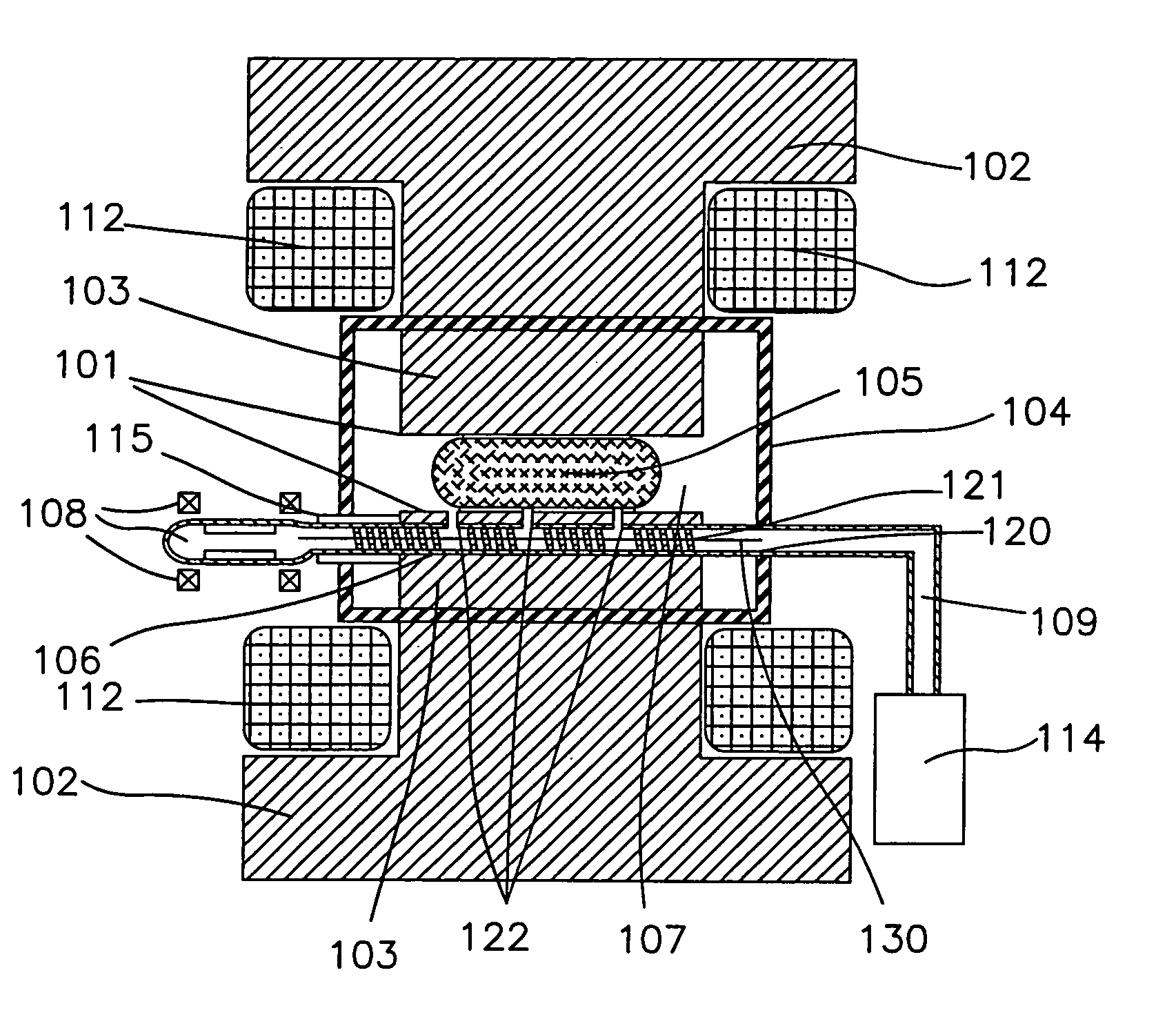
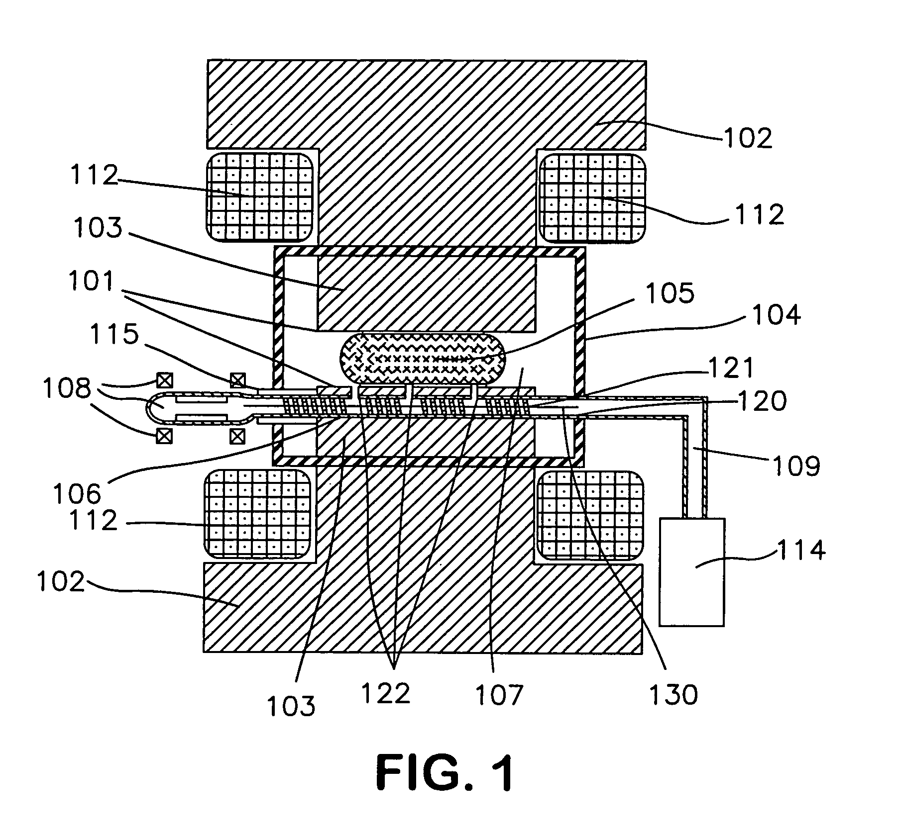
[0055]FIG. 1 illustrates a cross section of the magnetic pole of a deflection magnet. Although those skilled in the art will recognize that the pole surface, 101, may actually be part of the underlying magnetic return yoke, 102, in the preferred embodiment the surfaces of the poles, 103, are located within the vacuum chamber, 104, rather than outside it. The magnetic field is produced by the coils, 112. This allows the magnetic poles to be as close as needed to the trajectories of the ion beam, 105, without wasting distance for a wide vacuum envelope that needs thick walls to withstand atmospheric forces. Actively variable fields may be introduced using surface windings that are detailed in a companion patent application entitled “Broad Energy Range Ribbon Ion Beam Collimation Using a variable Gradient Dipole” by Kenneth H. Purser and Norman L. Turner.

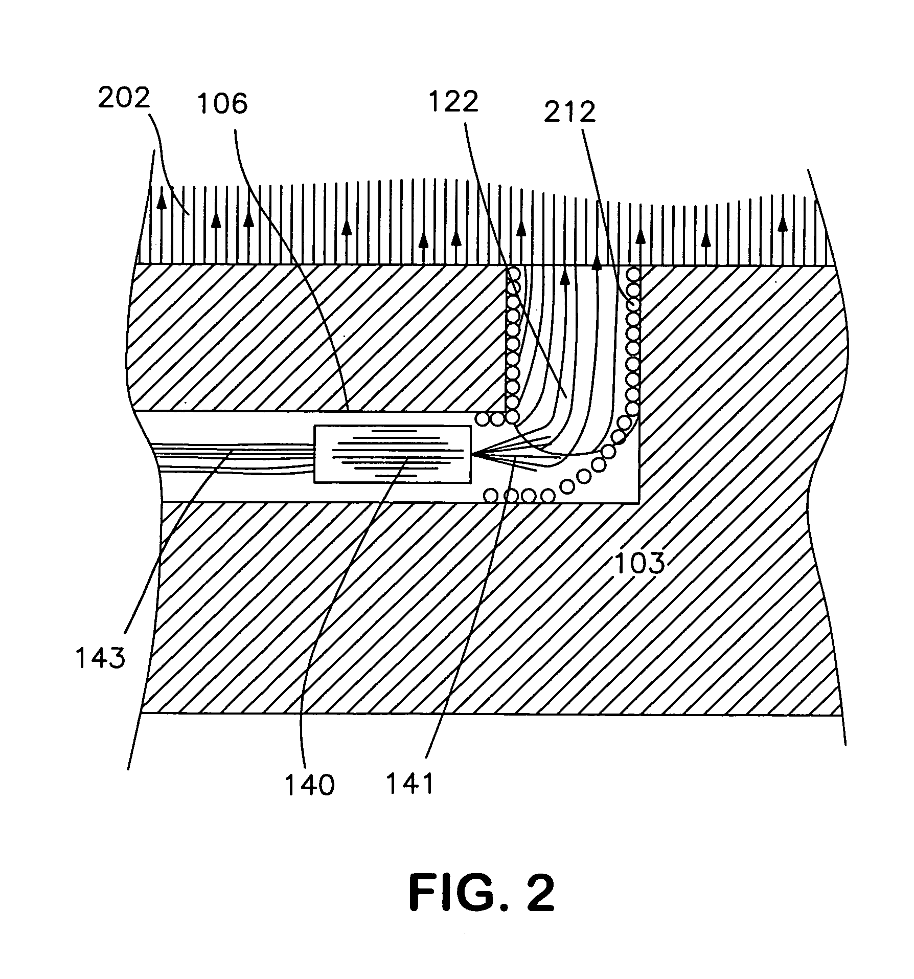
[0056]It can be seen that a modest diameter hole, 106, is drilled through the width of the pole plate, 103, defining a tunnel. While ...


PUM


Abstract

The fabrication of modern semiconducting integrated circuits often requires implantation steps that involve high currents of low-energy charged dopant atoms. When employing such beams, the addition of electrons or negative ions for neutralizing the effects of space charge is often crucial for achieving success. Without this supplement, ion beams can ‘blow-up’ causing loss of intensity and disruption of beam focusing. In the present disclosure, methods are presented for introducing and constraining neutralizing low-energy electrons and negative ions within the boundaries of ribbon beams within regions of magnetic field deflection. Apparatus is described for maintaining neutralization based upon a reduction of electron losses, plasma bridge connections and secondary electron production. As part of plasma introduction to the deflection region a novel cryogenic pumping apparatus selectively removes neutral atoms from a plasma stream.

Description

[0001]This Application claims priority to U.S. provisional patent application Ser. Nos. 60 / 637,625 filed Dec. 20, 2004 entitled “Improving Beam Neutralization in Low-Energy High-Current Implanters”; 60 / 638,848 filed Dec. 23, 2004 also entitled “Improving Beam Neutralization in Low-Energy High-Current Implanters”; 60 / 642,612 filed Jan. 10, 2005 also entitled “Improving Beam Neutralization in Low-Energy High-Current Implanters”; and 60 / 645,458 filed Jan. 19, 2005 also entitled “Improving Beam Neutralization in Low-Energy High-Current Implanters”, the disclosures of which are incorporated herein by reference in their entirety.FIELD OF INVENTION[0002]This invention relates to methods and apparatus used for low-energy high-current ion implantation using ribbon beams. Specifically, the invention improves the efficiency of space-charge neutralization using electrons or negative ions for minimizing the effects of space-charge disruption.BACKGROUND OF THE INVENTION[0003]Implantation, one of ...

Claims


Application Information

Patent Timeline
Patent Type & Authority Patents(United States)
IPC IPC(8): H01J37/317
CPCH01J37/3171H01J2237/057H01J2237/055H01J2237/0042H01J37/026H01J37/08
Inventor PURSER, KENNETH H.TURNER, NORMAN L.
Owner VARIAN SEMICON EQUIP ASSOC INC
Why Eureka
Try Eureka