
Method and device for performing cooling- or cryo-therapies for, e.g., angioplasty with reduced restenosis or pulmonary vein cell necrosis to inhibit atrial fibrillation employing microporous balloon

a technology of pulmonary vein cell necrosis and cooling-or-cryotherapy, which is applied in the direction of contraceptive devices, catheters, applications, etc., can solve the problems of lack of synchronization between heartbeat and pulse, circumferential tissue, and atrial fibrillation, and achieves the reduction or inhibition of the rate of restenosis, minimize or inhibit the biochemical events responsible, and the effect of robust design

Inactive Publication Date: 2008-11-11
ZOLL CIRCULATION
View PDF486 Cites 138 Cited by
  • Summary
  • Abstract
  • Description
  • Claims
  • Application Information

AI Technical Summary

Benefits of technology

[0010]The present invention provides an enhanced method and device to inhibit or reduce the rate of restenosis following angioplasty or stent placement. The invention is similar to placing an ice pack on a sore or overstrained muscle for a period of time to minimize or inhibit the biochemical events responsible for an associated inflammatory response. An embodiment of the invention generally involves placing a balloon-tipped catheter in the area treated or opened through balloon angioplasty immediately following angioplasty. A so-called “cryoplasty” balloon, which can have a dual balloon structure, may be delivered through a guiding catheter and over a guidewire already in place from a balloon angioplasty. The dual balloon structure has benefits described below and also allows for a more robust design. The balloon is porous so that an amount of ablation fluid is delivered to the tissue at the ablation site.
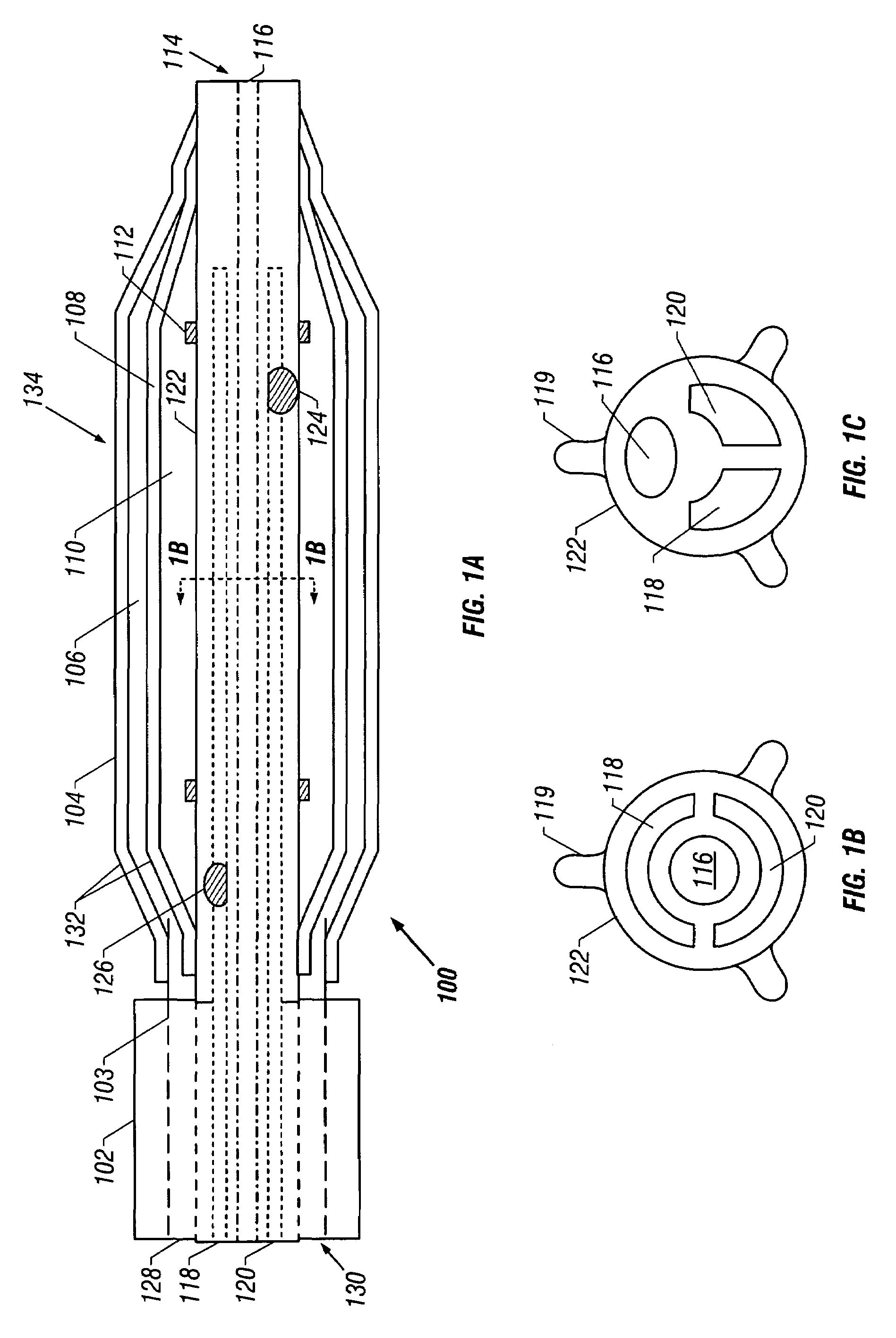
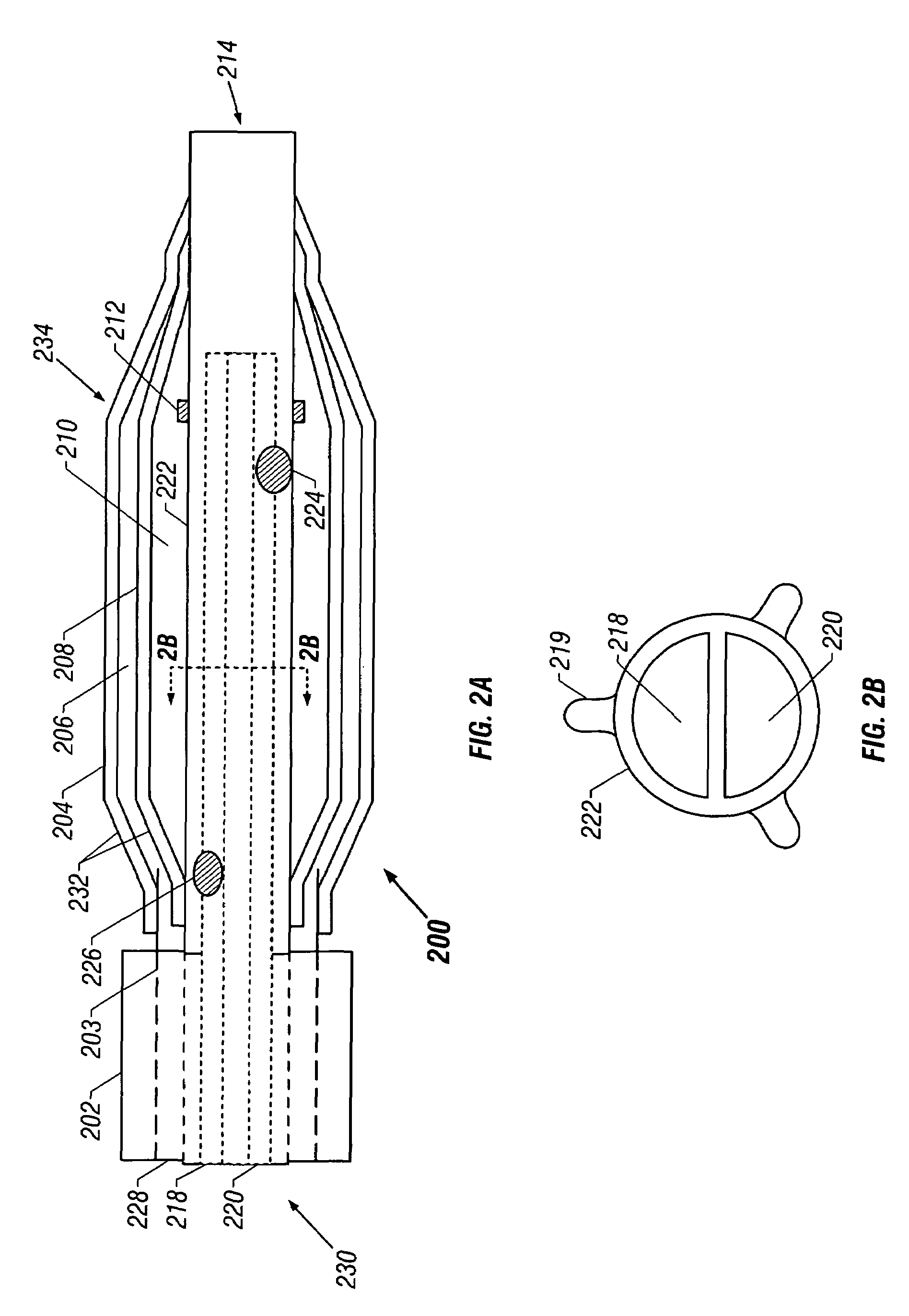
[0016]Variations of the invention may include one or more of the following. The inner tube may further define a guidewire lumen, a supply lumen, and a return lumen. The supply lumen may define a hole or skive such that a fluid flowing in the supply lumen may be caused to flow into a volume defined by the inner balloon, and the return lumen may define a hole or skive such that a fluid flowing in a volume defined by the inner balloon may be caused to flow into the return lumen. The guidewire lumen may extend from a proximal end of the inner tube to a distal end of the inner tube. The device may further comprise at least two radially extending tabs disposed around a circumference of the inner tube to substantially center the inner tube within the dual balloon. The device may further comprise at least one marker band disposed on the inner tube to locate a working region of the device at a desired location. The device may further comprise a source of chilled fluid having a supply tube and a return tube, the supply tube coupled in fluid communication to the supply lumen and the return tube coupled in fluid communication to the return lumen. A source of fluid may also be included, the source of fluid coupled in fluid communication to a volume between the inner balloon and the outer balloon. The fluid may be a perfluorocarbon such as Galden fluid. The fluid may also include contrast media. The size of the pores of the outer balloon may be in the micron range, so long as the pores do not prevent the balloon from achieving a pressure of about 1 to 2 atmospheres. The pores may be disposed in one of a variety of shapes, including a band, a helix, and so on. The use of just a single pore may be employed as well to minimize fluid loss while still allowing some conduction enhancement.
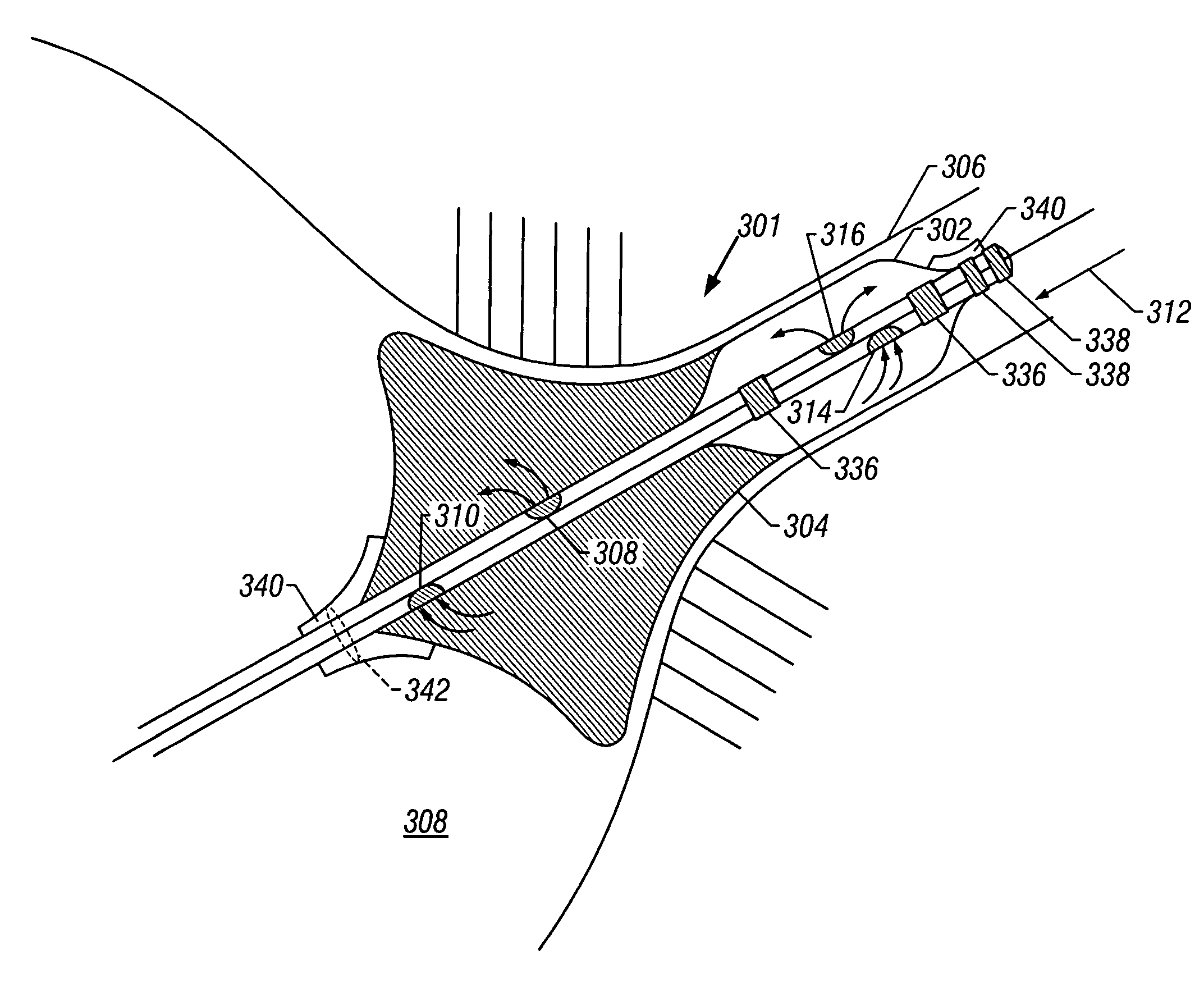
[0020]Variations of the method may include one or more of the following. The balloon may have a working region having a length of between about 5 mm and 10 mm. The method may further include inserting a wire having a needle point from the femoral vein into the right atrium and forming a hole using the needle point in the interatrial septum between the right atrium and the left atrium. A guide catheter may then be inserted into the right atrium. A guide wire may further be inserted through the guide catheter into the right atrium and further into a pulmonary vein. The catheter may then be disposed over the guidewire into a volume defined by the joint of the right atrium and the pulmonary vein. The size of the pores of the outer balloon may be in the micron range, so long as the pores do not prevent the balloon from achieving a pressure of about 1 to 2 atmospheres. The pores may be disposed in one of a variety of shapes, including a band, a helix, and so on. The use of just a single pore may be employed as well to minimize fluid loss while still allowing some conduction enhancement.
[0021]Advantages of the invention may include one or more of the following. The invention inhibits or reduces the rate of restenosis following a balloon angioplasty or any other type of vascular intervention. At least the following portions of the vascular anatomy can benefit from such a procedure: the abdominal aorta (following a stent or graft placement), the coronary arteries (following PTCA or rotational artherectomy), the carotid arteries (following an angioplasty or stent placement), as well as the larger peripheral arteries.
[0022]When the invention is used to treat atrial fibrillation, the following advantages inure. The cooled tissue is adherent to the heat transfer element and / or to the ablative fluid, increasing the heat transfer effected. Since very cold temperatures may be employed, the temperature gradient can be quite large, increasing the heat transfer rate. The ablative fluid that passes from the balloon to the tissue may assist the heat transfer conduction and the ensuing cell necrosis.
[0023]In both embodiments, heat transfer does not occur primarily or at all by vaporization of a liquid, thus eliminating a potential cause of bubbles in the body. Nor does cooling occur primarily or at all by a pressure change across a restriction or orifice, this simplifying the structure of the device. Thrombus formation and charring, associated with prior techniques, are minimized or eliminated.

Problems solved by technology

Another cardiological malady is atrial fibrillation.
Atrial fibrillation refers to very rapid irregular contractions of the atria of the heart resulting in a lack of synchronization between the heartbeat and the pulse.
The above technique is disadvantageous in that circumferential portions of the tissue, desired to be necrosed, are not in fact affected.
Other techniques, including RF ablation, are similarly inefficient.
Moreover, these techniques leave the necrosed portions with jagged edges, i.e., there is poor demarcation between the healthy and the necrosed tissue.
These edges can then cause electrical short circuits, and associated electrical irregularities, due to the high electric fields associated with jagged edges of a conductive medium.
The above technique is also disadvantageous in that heating is employed.
Heating is associated with several problems, including increased coagulum and thrombus formation, leading to emboli.
Finally, since tissues can only safely be heated to temperatures of less than or about 75° C.-85° C. due to charring and tissue rupture secondary to steam formation.
The thermal gradient thus induced is fairly minimal, leading to a limited heat transfer.
Another disadvantage that may arise during either cooling or heating results from the imperfections of the surface of the tissue at or adjacent to the point of contact with the cryoballoon (in the case of cooling).
As noted above, incomplete circumferential necrosis is often deleterious in treating atrial fibrillation and may well be further deleterious due to the necessity of future treatments.

Method used


Image

  • Method and device for performing cooling- or cryo-therapies for, e.g., angioplasty with reduced restenosis or pulmonary vein cell necrosis to inhibit atrial fibrillation employing microporous balloon
  • Method and device for performing cooling- or cryo-therapies for, e.g., angioplasty with reduced restenosis or pulmonary vein cell necrosis to inhibit atrial fibrillation employing microporous balloon
  • Method and device for performing cooling- or cryo-therapies for, e.g., angioplasty with reduced restenosis or pulmonary vein cell necrosis to inhibit atrial fibrillation employing microporous balloon

Examples


first embodiment

[0037]Referring to FIG. 1A, a catheter 100 is shown according to the invention. The catheter 100 has a proximal end 130 and a distal end 114. Of course, this figure is not necessarily to scale and in general use the proximal end 130 is far upstream of the features shown in FIG. 1A.

[0038]The catheter 100 may be used within a guide catheter 102, and generally includes an outer tube 103, a dual balloon 134, and an inner tube 122. These parts will be discussed in turn.

[0039]The guide catheter 102 provides a tool to dispose the catheter 100 adjacent the desired location for, e.g., angioplasty or reduction of atrial fibrillation. Typical guide catheter diameters may be about 6 French to 9 French, and the same may be made of polyether blockamide, polyamides, polyurethanes, and other similar materials. The distal end of the guide catheter is generally adjacent the proximal end of the dual balloon 134, and further is generally adjacent the distal end of the outer tube 103.

second embodiment

[0040]The ability to place the guide catheter is a significant factor in the size of the device. For example, to perform angioplasty in the carotid arteries, which have an inner diameter of about 4 to 6 mm, a suitably sized guide catheter must be used. This restricts the size of the catheter 100 that may be disposed within the guide catheter. A typical diameter of the catheter 100 may then be about 7 French or less or about 65 to 91 mils. In a second embodiment described below, a catheter for use in the coronary arteries is described. Of course, which catheter is used in which artery is a matter to be determined by the physician, taking into account such factors as the size of the individual patient's affected arteries, etc.

[0041]The outer tube 103 houses the catheter 100 while the latter traverses the length of the guide catheter 102. The outer tube 103 may have a diameter of about 0.4 French to 7 French, and the same may be made of polyether blockamide, poly-butylene terephtalate,...


PUM


Abstract

An enhanced method and device are provided to inhibit or reduce restenosis following angioplasty or stent placement. A porous balloon-tipped catheter is disposed in the area treated or opened through balloon angioplasty immediately following angioplasty. The balloon, which can have a dual balloon structure, may be delivered through a guiding catheter and over a guidewire already in place. A fluid such as a perfluorocarbon flows into the balloon to freeze the tissue adjacent the balloon, this cooling being associated with reduction of restenosis. A similar catheter may be used to reduce atrial fibrillation by inserting and inflating the porous balloon such that an exterior surface of the balloon, as well as a portion of the cold working fluid, from the microporosity contacts at least a partial circumference of the portion of the pulmonary vein adjacent the left atrium.

Description

CROSS-REFERENCE TO RELATED APPLICATIONS[0001]This application is a divisional of U.S. pat. application Ser. No. 09 / 932,402 filed on Aug. 17, 2001, now U.S. Pat. No. 6,685,732, entitled “Method And Device For Performing Cooling- Or Cryo-Therapies For, E.G., Angioplasty With Reduced Restenosis or Pulmonaiy Vein Cell Necrosis To Inhibit Afrial Fibrillation Employing Microporous Balloon”, which is a continuation-in-put of U.S. patent application No. 09087,599 filed Mar. 21, 2001, now U.S. Pat. No. 6,602,276, entitled “Method and Device for Performing Cooling-or Ciyo-Therapies for, e.g., Angioplasty with Reduced Restenosis or Pulmonary Vein Cell Necrosis to Inhibit Afrial Fibrillation” which is a continuation-in-part of U.S. patent application No.09 / 516,319, now abandoned, filed Mar. 1, 2000, entitled “Method and Device for Performing Cooling- or Cryo-Therapies for, e.g., Angioplasty with Reduced Restenosis or Pulmonary Vein Cell Necrosis to Inhibit Afrial Fibrillation” which is a contin...

Claims


Application Information

Patent Timeline
IPC IPC(8): A61B18/02A61B17/22A61B18/00A61B18/08A61F7/12
CPCA61B18/02A61F7/12A61B18/08A61B2017/22002A61B2017/22051A61B2017/22054A61B2018/00023A61B2018/00041A61B2018/0022A61B2018/0212A61B2018/0262A61F2007/126
Inventor KRAMER, HANS W.
Owner ZOLL CIRCULATION
Learn More