Apparatus for performing heat-exchanging chemical reactions

a technology of apparatus and heat exchange, applied in lighting, heating apparatus, laboratory glassware, etc., can solve the problems of long processing time, inefficiency of processes requiring precise temperature control, and affecting the detection of side products, so as to improve detection sensitivity, improve detection efficiency, and facilitate the effect of cooling and heating mixtures

Inactive Publication Date: 2008-12-09
CEPHEID INC
View PDF39 Cites 19 Cited by
  • Summary
  • Abstract
  • Description
  • Claims
  • Application Information

AI Technical Summary

Benefits of technology

[0012]The present invention overcomes the disadvantages of the prior art by providing an improved apparatus for thermally controlling and optically interrogating a reaction mixture. In contrast to the prior art instruments described above, the apparatus of the present invention permits extremely rapid heating and cooling of the mixture, ensures optimal thermal transfer between the mixture and heating or cooling elements, provides real-time optical detection and monitoring of reaction products with increased detection sensitivity, and is easily configured for automated, high throughput applications. The apparatus is useful for performing heat-exchanging chemical reactions, such as nucleic acid amplification.
[0014]In the preferred embodiment, the reaction vessel includes first and second flexible sheets attached to opposite sides of the rigid frame to form opposing major walls of the chamber. In this embodiment, the apparatus includes first and second thermal surfaces formed by first and second opposing plates positioned to receive the chamber of the vessel between. When the pressure in the chamber is increased, the flexible major walls expand outwardly to contact and conform to the inner surfaces of the plates. A resistive heating element, such as a thick or thin film resistor, is coupled to each plate for heating the plates. In addition, the apparatus includes a cooling device, such as a fan, for cooling the plates. Each of the plates is preferably constructed of a ceramic material and has a thickness less than or equal to 1 mm for low thermal mass. In particular, it is presently preferred that each of the plates have a thermal mass less than about 5 J / ° C., more preferably less than 3 J / ° C., and most preferably less than 1 J / ° C. to enable extremely rapid heating and cooling rates.
[0016]The pressurization of the chamber ensures that the flexible major walls of the vessel are forced to conform to the inner surfaces of the plates, thus guaranteeing optimal thermal contact between the major walls and the plates. In the preferred embodiment, the device for increasing pressure in the chamber comprises a plunger which is inserted into the channel to compress gas in the vessel and thereby increase pressure in the chamber. The plunger preferably has a pressure stroke in the channel sufficient to increase pressure in the chamber to at least 2 psi of above the ambient pressure external to the vessel, and more preferably to a pressure in the range of 8 to 15 psi above the ambient pressure. In a preferred embodiment, the length of the pressure stroke is controlled by one or more pressure control grooves formed in the inner surface of the frame that defines the channel. The pressure control grooves extend from the port to a predetermined depth in the channel to allow gas to escape from the channel and thereby prevent pressurization of the chamber until the plunger reaches the predetermined depth. When the plunger reaches the predetermined depth, it establishes a seal with the walls of the channel and begins the pressure stroke. The pressure control grooves provide for highly controllable pressurization of the chamber and help prevent misalignment of the plunger in the channel.
[0018]In another embodiment of the invention, the pressurization of vessel is performed by a pick-and-place machine having a machine head for addressing the vessel. The machine head has an axial bore for communicating with the channel. The pick-and-place machine also includes a pressure source in fluid communication with the bore for pressurizing the chamber of the vessel through the bore. In this embodiment, the apparatus also preferably includes a disposable adapter for placing the bore in fluid communication with the channel. The adapter is sized to be inserted into the channel such that the adapter establishes a seal with the walls of the channel. The disposable adapter preferably includes a valve (e.g., a check valve) for preventing fluid from escaping from the vessel.
[0021]The apparatus of the present invention permits real-time monitoring and detection of reaction products in the vessel with improved optical sensitivity. In the preferred embodiment, at least two of the side walls of the chamber are optically transmissive and angularly offset from each other, preferably by an angle of about 90°. The apparatus further comprises an optics system for optically interrogating the mixture contained in the chamber through the optically transmissive side walls. The optics system includes at least one light source for exciting the mixture through a first one of the side walls, and at least one detector for detecting light emitted from the chamber through a second one of the side walls.
[0022]Optimum optical sensitivity may be attained by maximizing the optical sampling path length of both the light beams exciting the labeled analytes in the reaction mixture and the emitted light that is detected. The thin, wide reaction vessel of the present invention optimizes detection sensitivity by providing maximum optical path length per unit analyte volume. In particular, the vessel is preferably constructed such that the ratio of the width of the chamber to the thickness of the chamber is at least 4:1, and such that the chamber has a thickness in the range of 0.5 to 2 mm. These parameters are presently preferred to provide a vessel having a relatively large average optical path length through the chamber, while still keeping the chamber sufficiently thin to allow for extremely rapid heating and cooling of the reaction mixture.

Problems solved by technology

First, due to the large thermal mass of a metal block, the heating and cooling rates in these instruments are limited to about 1° C. / sec resulting in longer processing times. For example, in a typical PCR application, fifty cycles may require two or more hours to complete.
With these relatively slow heating and cooling rates, some processes requiring precise temperature control are inefficient.
For example, reactions may occur at the intermediate temperatures, creating unwanted and interfering side products, such as PCR “primer-dimers” or anomalous amplicons, which are detrimental to the analytical process.
Poor control of temperature also results in over-consumption of expensive reagents necessary for the intended reaction.
A second disadvantage of these conventional instruments is that they typically do not permit real-time optical detection or continuous optical monitoring of the chemical reaction.
Since all of the reaction sites are sequentially excited by a single laser and since the fluorescence is detected by a single spectrometer and photomultiplier tube, simultaneous monitoring of each reaction site is not possible.
There are, however, several disadvantages to this device in its use of a micromachined silicon sleeve.
A first disadvantage is that the brittle silicon sleeve may crack and chip.
A second disadvantage is that it is difficult to micromachine the silicon sleeve with sufficient accuracy and precision to allow the sleeve to precisely accept a plastic tube that holds the sample.
Consequently, the plastic tube may not establish optimal thermal contact with the silicon sleeve.
Unfortunately, this instrument is not easily configured for commercial, high throughput diagnostic applications.
Heat sealing the film or foil to the vessel seals the port and collapses an end of the channel to reduce the volume of the vessel and thereby increase pressure in the chamber.

Method used


Image

  • Apparatus for performing heat-exchanging chemical reactions
  • Apparatus for performing heat-exchanging chemical reactions
  • Apparatus for performing heat-exchanging chemical reactions

Examples


Embodiment Construction

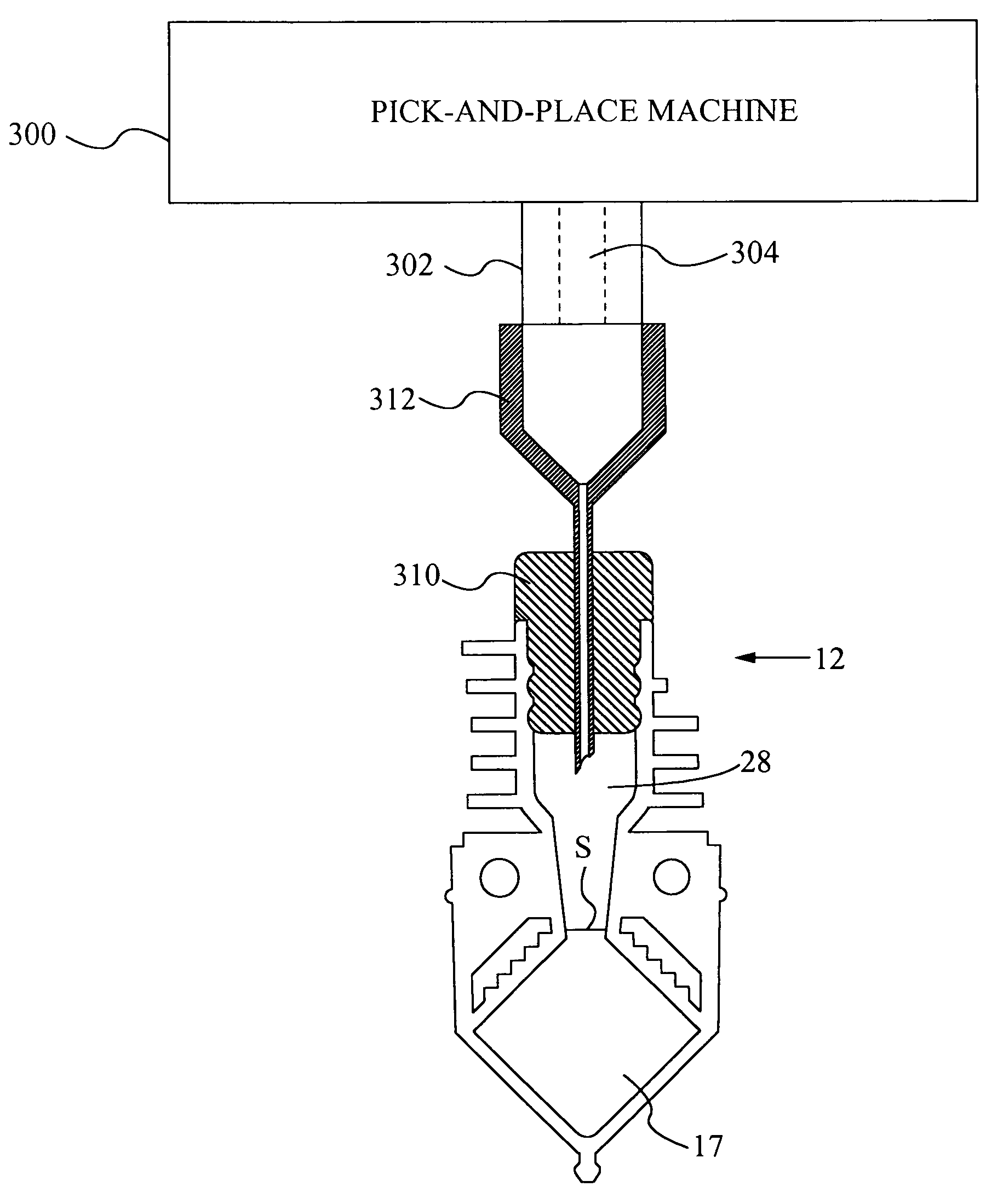
[0061]The present invention provides an apparatus for thermally controlling and optically interrogating a reaction mixture, e.g., a sample mixed with one or more chemicals or reagents. The sample may also be mixed with diluents or buffers. The sample may be an aqueous solution containing particles, cells, microorganisms, ions, or small and large molecules, such as proteins and nucleic acids, etc. In a particular use, the sample may be a bodily fluid (e.g., blood, urine, saliva, sputum, seminal fluid, spinal fluid, mucus, or other bodily fluids). Alternatively, the sample may be a solid made soluble in a liquid or the sample may be an environmental sample such as ground or waste water, soil extracts, pesticide residues, or airborne spores placed in a liquid.

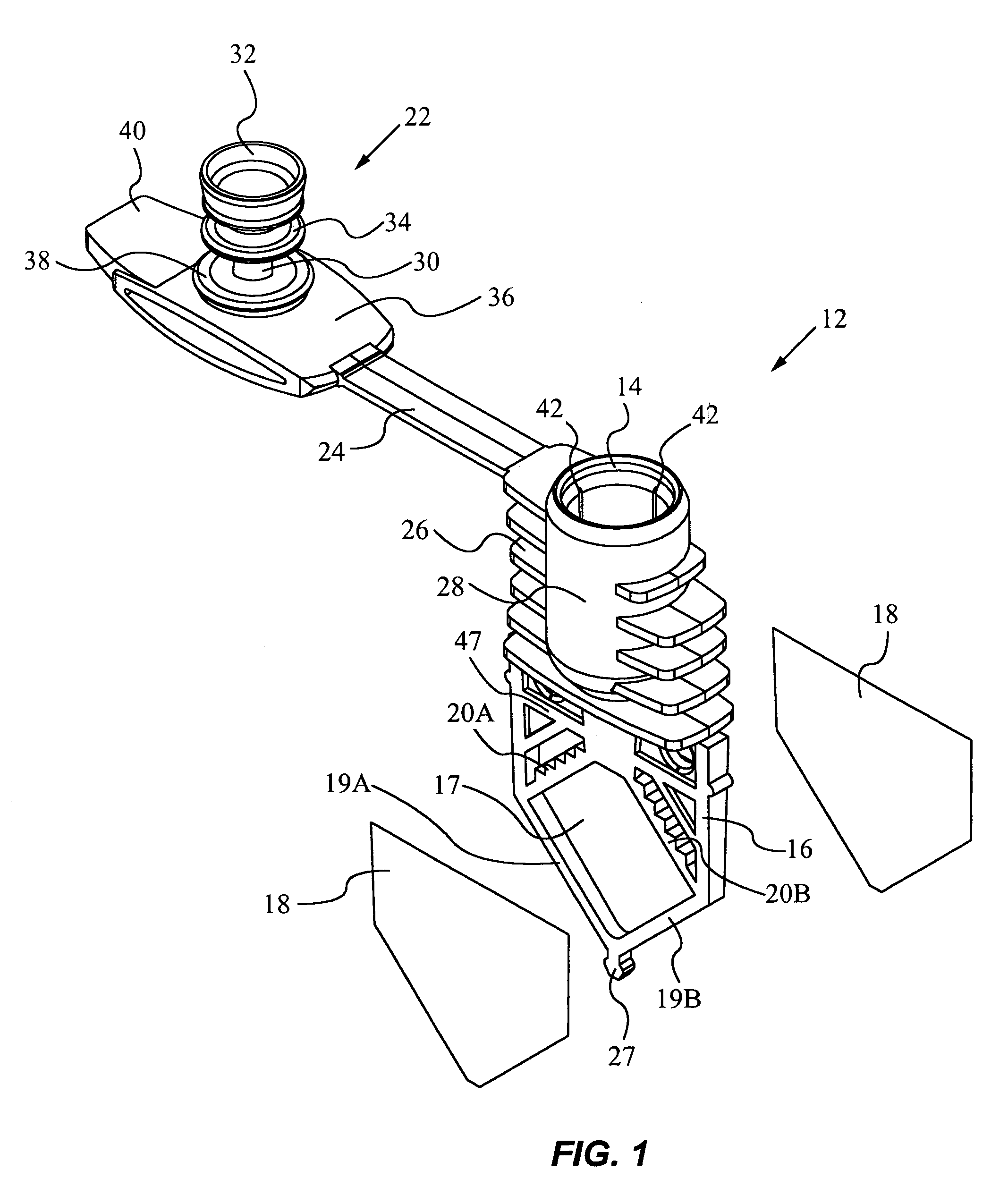
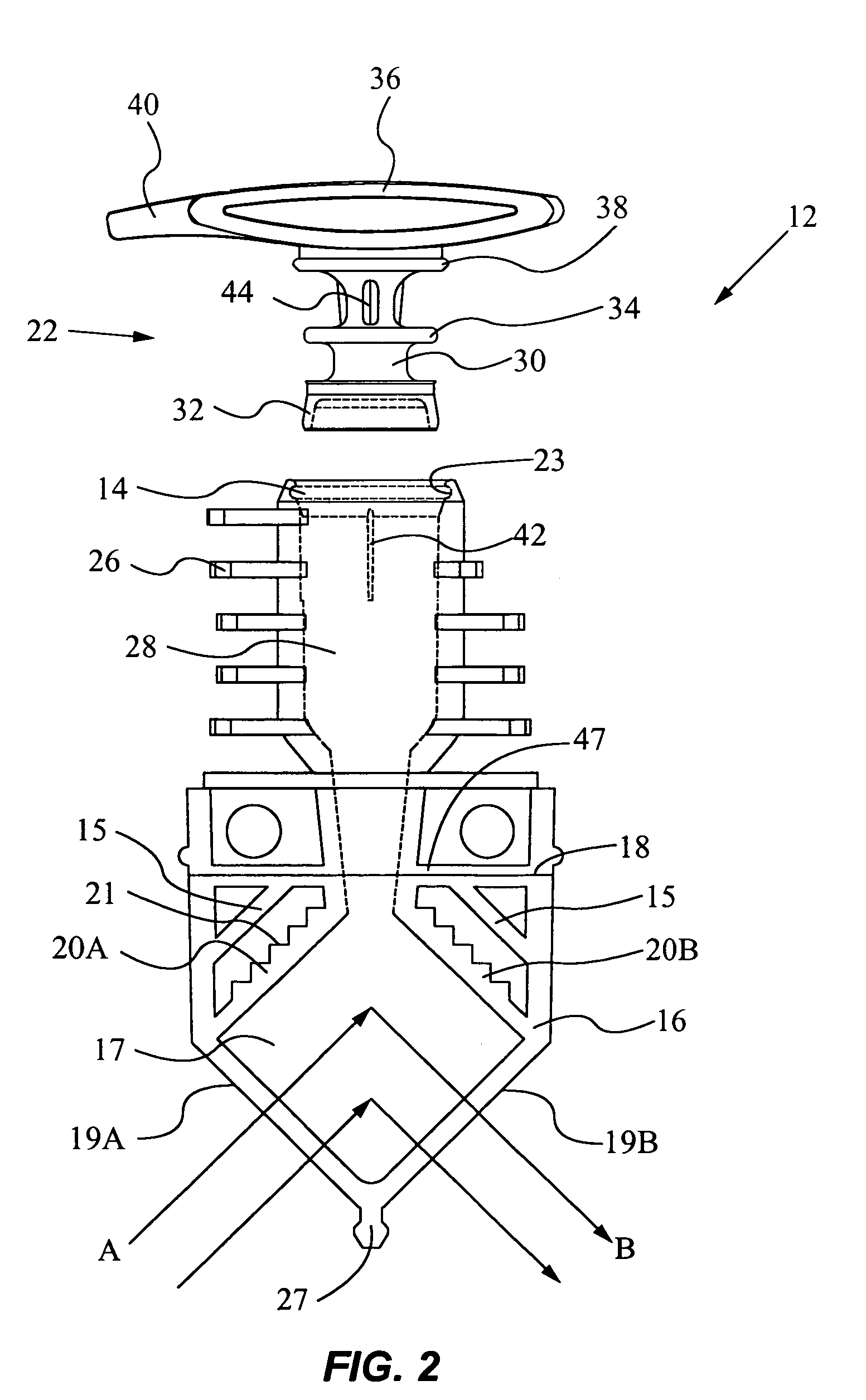
[0062]In a preferred embodiment, the apparatus includes a reaction vessel for holding the mixture and a heat-exchanging module into which the vessel is inserted for thermal processing and optical detection. The heat-exchanging mod...


PUM

PropertyMeasurementUnit
thicknessaaaaaaaaaa
pressureaaaaaaaaaa
thicknessaaaaaaaaaa

Abstract

An apparatus for controlling the temperature of a reaction mixture contained in a chamber of a reaction vessel comprises a thermal surface for contacting a flexible wall of the chamber and an automated machine for increasing the pressure in the chamber. The pressure increase in the chamber is sufficient to force the flexible wall to conform to the thermal surface for good thermal conductance. The apparatus also includes at least one thermal element for heating or cooling the surface to induce a temperature change within the chamber.

Description

RELATED APPLICATION INFORMATION[0001]This application is a divisional of U.S. patent application Ser. No. 09 / 468,690, filed Dec. 21, 1999, which is a continuation in part of U.S. application Ser. No. 09 / 194,374, filed Jul. 25, 2000, now U.S. Pat. No. 6,565,815, filed as a national phase stage entry (371) of international application PCT / US98 / 03962, filed Mar. 2, 1998. All of these applications are incorporated by reference herein for all purposes.FIELD OF THE INVENTION[0002]The present invention relates to an apparatus for performing heat-exchanging, chemical reactions and for optically detecting a reaction product.BACKGROUND OF THE INVENTION[0003]There are many applications in the field of chemical processing in which it is desirable to precisely control the temperature of reaction mixtures (e.g., biological samples mixed with chemicals or reagents), to induce rapid temperature changes in the mixtures, and to detect target analytes in the mixtures. Applications for such heat-exchan...

Claims


Application Information

Patent Timeline
Patent Type & Authority Patents(United States)
IPC IPC(8): G01N15/06B01L3/02G01N1/10G01N21/00G01N33/00B01J19/00B01L3/00B01L7/00B01L9/00C12Q1/68F28F13/00G01N21/03G01N35/00G01N35/04
CPCB01J19/0093B01L3/508B01L7/52F28F13/00G01N21/0332Y10T436/2575B01J2219/00873B01J2219/00963B01J2219/0097B01L9/00B01L2300/042B01L2300/0858B01L2300/1827F28D2021/0077G01N35/0099G01N2035/00376G01N2035/0405B01J2219/00788
Inventor CHANG, RONALDDORITY, DOUGLAS B.CHRISTEL, LEE A.YUAN, ROBERTPETERSEN, KURT E.
Owner CEPHEID INC
Why Eureka
Try Eureka