Ocean power harvester

a power harvester and ocean technology, applied in the field of energy, can solve the problems of increasing the absolute cost of carbon-based fuels, alaska and the north sea are about to enter a period of irreversible decline, and the overall efficiency of the power harvester is more important than the overall surface area

Inactive Publication Date: 2009-04-28
CATLIN CHRIS S
View PDF44 Cites 30 Cited by
  • Summary
  • Abstract
  • Description
  • Claims
  • Application Information

AI Technical Summary

Benefits of technology

[0012]There are approximately twelve generic types of wave energy conversion systems. A wave energy converter may be placed in the ocean in various possible situations and locations. It may be floating or submerged completely in the sea offshore or it may be located on the shore or on the sea bed in relatively shallow water. An energy converter on the sea bed may be completely submerged, it may extend above the sea surface, or it may be an energy converter system placed on an offshore platform. Apart from wave-powered navigation buoys, however, most of the prototypes have been placed at or near the shore. Some systems extract energy from surface waves. Others extract energy from pressure fluctuations below the water surface or from the full wave. Some systems are fixed in position and let waves pass by them, while others follow the waves and move with them. Some systems concentrate and focus waves, which increases their height and their potential for conversion to electrical energy. All the current competing technologies convert wave action into energy by providing some way for the wave to transfer its kinetic energy to a piston or turbine, either storing this energy briefly or passing it immediately into a generation device.

Problems solved by technology

This is when energy prices will skyrocket.
Even after massive investment by the oil companies in non-OPEC, the areas in Alaska and the North Sea are about to enter a period of irreversible decline.
The search for new sources of energy is now one of the most important challenges for the new century.
The absolute cost of carbon-based fuels, particularly petroleum, has increased dramatically over the last decade along with the political and military consequences caused by the world's increasing reliance on it.
Also we do not want an energy producing technology that fills up the countryside with machinery eyesores and noise.
Oil certainly does not meet these new requirements, nor does ethanol, biomass or even wind or conventional hydropower.
Many of the Third World countries suffer from polluted cities affecting their tourism, high petroleum import costs and growing power grid failures weakening their economies and their fragile currencies.
But displacement type wave energy converters are much more expensive and can only pull energy out a small surface area.
Inefficient multiple energy conversion systems are currently used to convert potential energy to usable kinetic energy.
Another major problem is location.
It places machinery under constant attack from shock, moisture, salt, debris, biological forms and cold temperatures.
The second part of this problem is the need to place wave power generation systems in high wave power areas which are out at sea.
This requires long power transmission infrastructure which is costly and suffer from considerable power loss in the lines.
Current on shore based coastal wave energy device systems are costly and eye sores.
The ocean based systems are also dangerous to navigation.
The offshore type sited in the most powerful wave areas need expensive deep ocean anchoring systems and are exposed to the worst storm conditions.
(d) Due to the complexity and size of many of the devices their surfaces and working parts are vulnerable to fouling from floating debris and marine growth;
(e) Many devices require complex mooring systems which are costly to install and may ensnare ocean wildlife;
(f) Some devices are not self-righting;
(g) Some devices remain on the surface in storm conditions making them vulnerable;
(h) Many devices have a large number of parts which increase the chances of breakdowns and increase build costs;
(i) Many devices are composed almost entirely of custom manufactured parts which increases overall costs and makes scalability harder to achieve;
(j) Most devices are designed to operate individually off their own dedicated mooring system which, reduces their overall surface area and increases build costs;
(k) Due to their complexity many devices have internal, inertial / mass and surface frictions;
(l) Many devices have complicated electrical systems requiring expensive and vulnerable seals;
(n) Most devices cannot be fabricated of recycled materials which decreases their total lifecycle energy costs;
(o) Most devices are stand alone devices which do not offer reduced wave areas for fish trawlers and private ships;
(p) Most devices are not designed for mass production to reduce costs;
(r) Many devices cannot function as a storm surge barriers but cannot because the moored devices have gaps between them;
(s) Many devices do not adapt well to fresh water production;
(z) Most devices require closely machined high tensile parts which are expensive and difficult to mass produce;
(bb) Most devices cannot meet the global strategy to deal with the successful commercialization of a low density global energy source.
(cc) Most wave energy converters are not smart enough to adapt instantly to the changing ocean conditions so that they can absorb the maximum amount of energy while at the same time able to reduce their energy profile to be able to survive massive storm conditions.
(w) the device has a significant amount of hydrodynamic dampening in relation to its displacement;

Method used


Image

  • Ocean power harvester
  • Ocean power harvester
  • Ocean power harvester

Examples


Embodiment Construction

FIGS. 1A and 1B—Preferred Embodiment

[0121]The following is a detailed description of illustrative embodiments of the present invention. As these embodiments of the present invention are described with reference to the aforementioned drawings, various modifications or adaptations of the methods or specific structures described may become apparent to those skilled in the art. All such modifications, adaptations, or variations that rely upon the teachings of the present invention and through these teachings have advanced the art, are considered to be within the spirit and scope of the present invention.

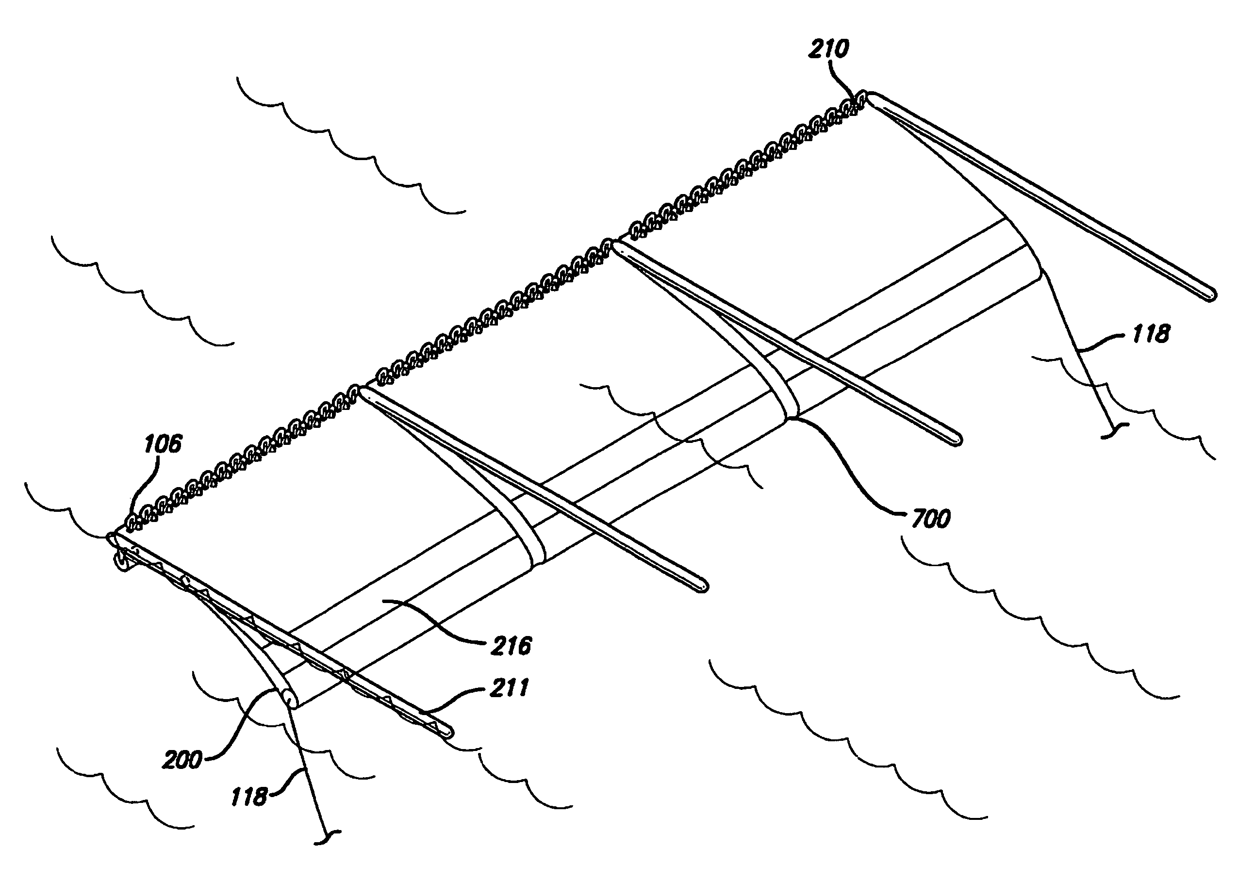
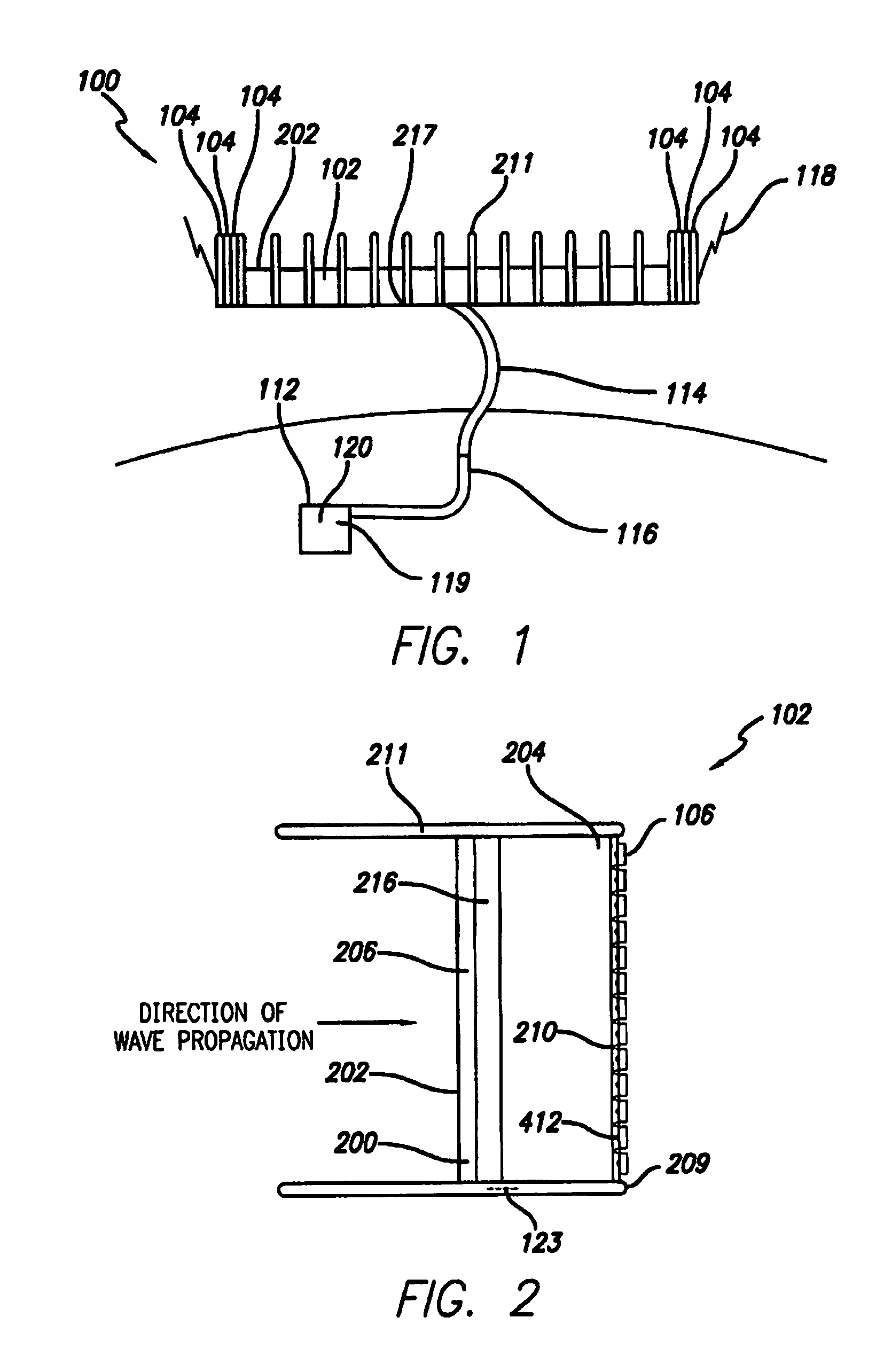
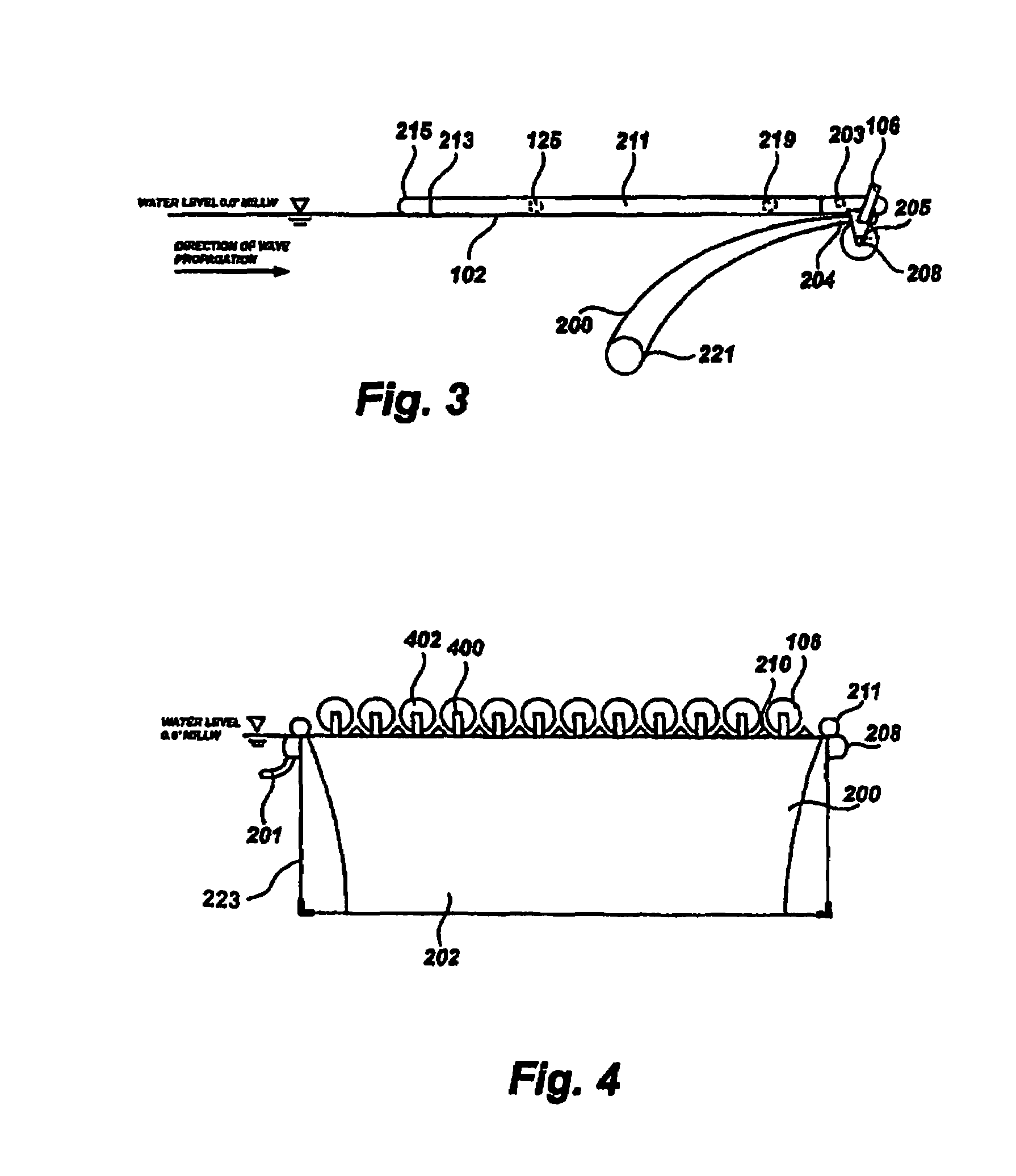
[0122]FIG. 1 is a top view of a long, semi-submerged floating Array of Devices 100 composed of a plurality of individual and identical Ocean Energy Modules (the invention) 102 deployed and connected beam to beam. Each end of the Array of Devices 100, composed of several Ocean Energy Modules 102, is moored to the ocean bottom through high buoyancy Support Vessels 104. The individual Ocean...


PUM


Abstract

An improved ocean energy converter having a semi-submerged device designed to harvest energy from the ocean. Each device is connected to others to form long lines forming an interconnected array of ocean energy devices that are anchored at right angles to the prevailing ocean waves. The front and back sections of each energy module have internal ballast. Each device has a submerged inverse curved wing sections attached to floating stabilizer tubes. The trailing edge of the wings has several struts attached which support propellers that drive internal air compressors. The air compressors are connected together and connected to the other air compressors in the array of devices and those in turn are connected to a high pressure line leading underwater to an onshore air turbine electric generator connected to the local power grid.

Description

CROSS-REFERENCE TO RELATED APPLICATIONS[0001]This application claims the benefits of PPA Ser. No. 60 / 692,220, filed Jun. 20, 2005 by the present inventor.FEDERALLY SPONSORED RESEARCH[0002]Not ApplicableSEQUENCE LISTING OR PROGRAM[0003]Not ApplicableBACKGROUND OF THE INVENTION[0004]1. Field of Invention[0005]This invention relates to the field of energy, specifically to a device that can produce mechanical and electric energy from ocean wave sources with maximum efficiency, minimum cost and maintenance without producing any greenhouse gases (GHG) emissions, directly or indirectly.[0006]2. Prior Art[0007]The Industrial Age began little more than 150 years ago powered primarily by wood, coal and petroleum. Today, our energy economy seems to be humming along like a perpetual motion machine. Billions of people enjoy an unprecedented standard of living and nations are floating in rivers of wealth, in large part because, around the world, the energy industry has built an enormous network o...

Claims


Application Information

Patent Timeline
Patent Type & Authority Patents(United States)
IPC IPC(8): F03B13/10F03B13/12H02P9/04
CPCF03B13/183F03B13/188F03B13/22F05B2240/40Y02E10/38Y02E10/30
Inventor CATLIN, CHRIS S
Owner CATLIN CHRIS S
Why Eureka
Try Eureka