Ceramic honeycomb filter and its production method

a honeycomb filter and ceramic technology, applied in the field of ceramic honeycomb filters, can solve the problems of increased pressure loss and engine power, difficult regeneration of honeycomb filters, and reduced capturing function, so as to achieve efficient regeneration

Inactive Publication Date: 2009-08-25
HITACHI METALS LTD
View PDF18 Cites 63 Cited by
  • Summary
  • Abstract
  • Description
  • Claims
  • Application Information

AI Technical Summary

Benefits of technology

[0014]Accordingly, an object of the present invention is to provide a ceramic honeycomb filter surely having space on an exhaust gas-introducing side upstream of plugs, so that regeneration is conducted efficiently in the entire filter without pressure loss.

Problems solved by technology

As particulates are continuously captured in the honeycomb filter 50, the pores of the cell walls 56 are clogged, resulting in drastic decrease in a capturing function and thus increase in a pressure loss and decrease in engine power.
However, when particulates captured in the conventional honeycomb filter are burned by an electric heater or a burner, only small amounts of particulates are attached in an upstream region, so that heat generated by the burning of particulates is not sufficient to keep the self ignition of particulates, failing to burn particulates in a downstream region and thus resulting in difficulty in the regeneration of the honeycomb filter.
Also, when regeneration is carried out by a microwave system as shown in JP 59-126022 A, for instance, a portion of the filter near the air supply side is cooled by air supplied, so that the temperature elevation of particulates is hindered, resulting in difficulty in the burning of particulates and narrowing of a region in which the burning of particulates occurs, and thus difficulty in effective regeneration of the entire honeycomb filter.
As a result, when air necessary for the burning of particulates is supplied from an exhaust gas inlet side to repeat the capturing of particulates and regenerating the filter, unburned particulates are so accumulated near an end surface of the filter that flow paths open on an exhaust gas inlet side are clogged, thereby losing a particulates-capturing function and resulting in extreme decrease in a filter-regenerating function.
It has been found, however, that when a honeycomb filter having a structure, in which plugs on an exhaust gas inlet side are disposed inside an inlet end of the filter as shown in FIGS. 3 and 4, is actually produced, the following problems occur.
Because it is difficult to surely have space on the upstream side of the plugs on the exhaust gas-introducing side when the honeycomb filter thus formed is actually used to capture particulates, the honeycomb filter cannot exhibit functions of capturing particulates and preventing heat dissipation as expected, failing to efficiently carry out the regeneration of the entire filter, and resulting in a large pressure loss.
In addition, because the degree of solidification of a slurry differs in every flow path, spaces upstream of the inlet-side plugs have different volumes, resulting in uneven pressure loss among the honeycomb filters, and decrease in the production yield of honeycomb filters.

Method used


Image

  • Ceramic honeycomb filter and its production method
  • Ceramic honeycomb filter and its production method
  • Ceramic honeycomb filter and its production method

Examples


example 1

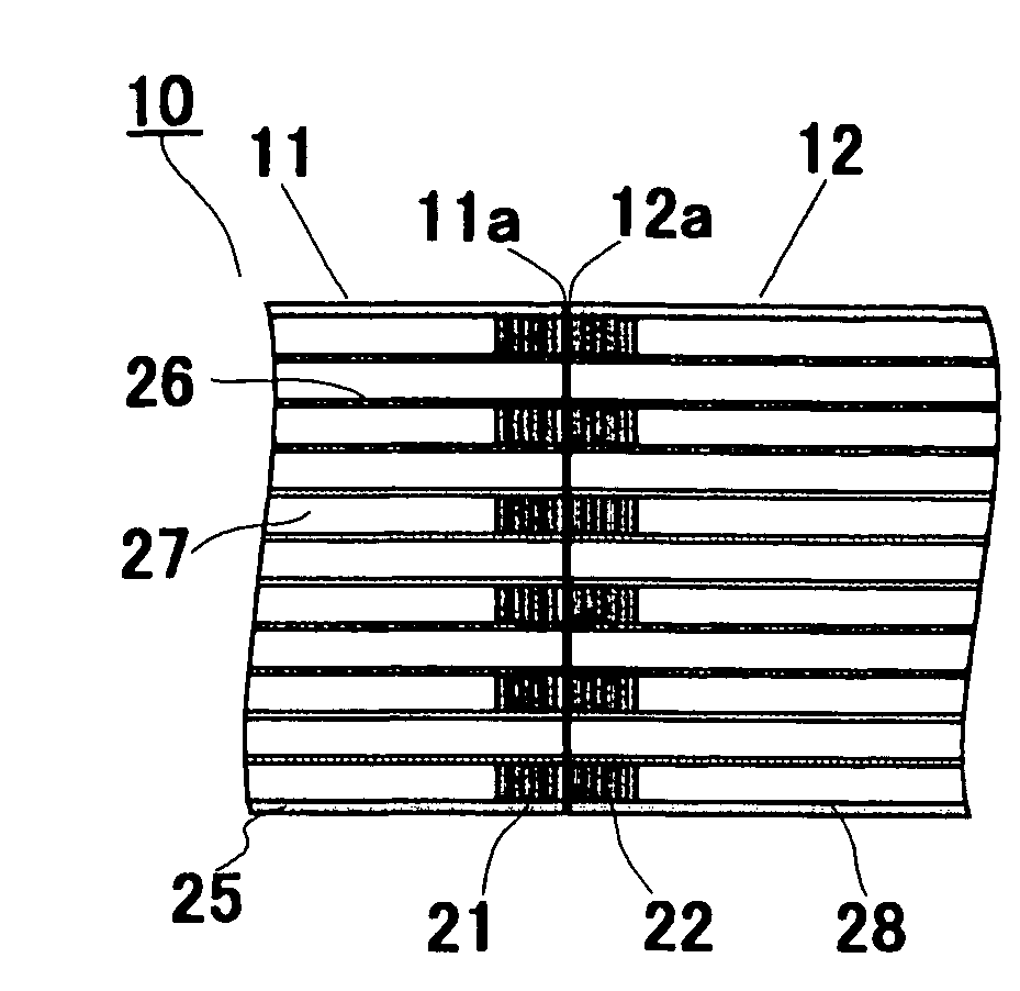
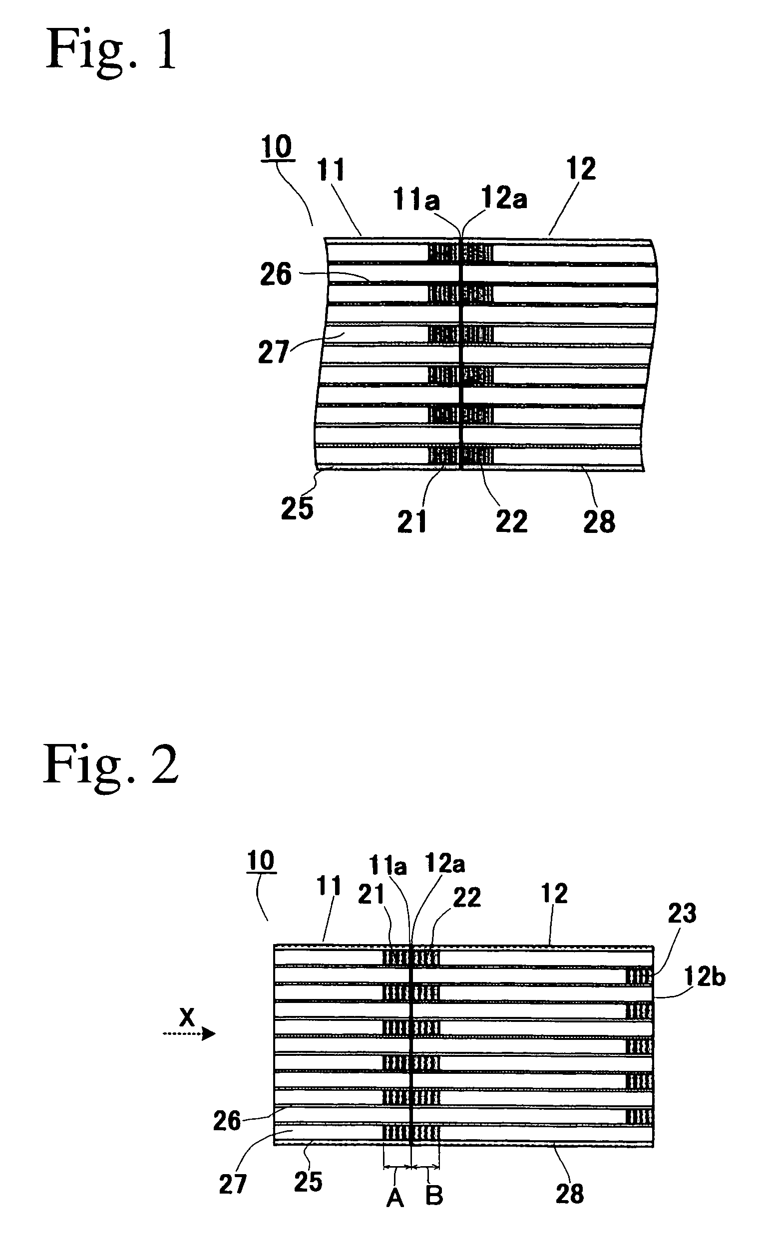
[0070]The ceramic honeycomb filter 10 of Example 1 shown in FIG. 2 is made of a cordierite ceramic, having an outer diameter of 267 mm, a length of 304.5 mm, a cell wall thickness of 0.3 mm, a cell wall pitch of 1.5 mm, a cell wall porosity of 65%, and an average pore diameter of 22 μm. Inlet-side plugs were positioned 92 mm from the inlet end. The ceramic honeycomb filter 10 was constituted by integrally bonding a honeycomb structure 11 having plugs 21 at one end to a ceramic honeycomb structure 12 having plugs 22, 23 at both ends, with these plugs aligned in the direction of the flow paths 27.

[0071]A cordierite-forming material powder comprising powders of kaolin, talc, fused silica, aluminum hydroxide, alumina, etc. was fully dry-mixed with methylcellulose as a molding aid, and graphite and an organic foaming agent as pore-forming agents, and then mixed with water, and further fully blended to form a ceramic material with moldable consistency. This ceramic material was extrusion-...

example 2

[0076]The ceramic honeycomb filter 10 of Example 2 shown in FIG. 11(b) was made of cordierite ceramic, having an outer diameter of 267 mm, a length of 304.8 mm, a cell wall thickness of 0.3 mm, and a cell wall pitch of 1.5 mm, the cell walls 26 having a porosity of 63% and an average pore size of 21 μm. The inlet-side plugs were positioned 92 mm from the inlet end. The ceramic honeycomb filter 10 was constituted by integrally bonding a honeycomb structure 11 having plugs 21 at one end to a ceramic honeycomb structure 12 having plugs 22, 23 at both ends, with these plugs aligned in the direction of the flow paths 27.

[0077]The ceramic honeycomb filter 10 was produced as shown in FIGS. 9(a)-(g). FIG. 9(a) shows a green body 1 extruded in the form of a honeycomb and dried, FIG. 9(b) shows a honeycomb structure sintered after a peripheral portion of the extruded green body 1 was removed by machining, FIG. 9(c) shows honeycomb structures 11, 12 obtained by cutting the sintered honeycomb s...

example 3

[0094]The ceramic honeycomb filter 10 of Example 3 shown in FIGS. 14(a) and 14(b) was made of cordierite ceramic, having an outer diameter of 267 mm, a length of 304.3 mm, a cell wall thickness of 0.3 mm, and a cell wall pitch of 1.5 mm, the cell walls 26 having a porosity of 65%, an average pore size of 22 μm, and a surface roughness of 45 μm. The inlet-side plugs were positioned 92 mm from the inlet end. The ceramic honeycomb filter 10 was constituted by integrally bonding a first honeycomb structure 11 having plugs 21 at one end to a ceramic honeycomb structure 12 having plugs 22, 23 at both ends, with these plugs aligned in the direction of the flow paths 27.

[0095]The ceramic honeycomb filter 10 was produced as shown in FIGS. 16(a)-(f). FIG. 16(a) shows a honeycomb structure 1 after sintering, FIG. 16(b) shows a honeycomb structure 1 with inclined cell walls, which was obtained by removing a peripheral portion from the honeycomb structure 1 of FIG. 16(a), FIG. 16(c) shows honeyc...


PUM

PropertyMeasurementUnit
depthaaaaaaaaaa
widthaaaaaaaaaa
widthaaaaaaaaaa

Abstract

A ceramic honeycomb filter comprising pluralities of ceramic honeycomb structures each having large numbers of flow paths partitioned by cell walls, which are bonded in the direction of the flow paths, predetermined flow paths being sealed by plugs, plugs formed at one end of at least one honeycomb structure being bonded to at least part of plugs formed at one end of a honeycomb structure adjacent to the end of this honeycomb structure.

Description

FIELD OF THE INVENTION[0001]The present invention relates to a ceramic honeycomb filter for capturing particulates in an exhaust gas from a diesel engine.BACKGROUND OF THE INVENTION[0002]From the aspect of protecting global environment, a ceramic honeycomb filter (hereinafter referred to simply as “honeycomb filter”) constituted by a ceramic honeycomb structure (hereinafter referred to simply as “honeycomb structure”) having both ends on exhaust gas-introducing and -exiting sides sealed alternately is used to remove carbon-based particulates from an exhaust gas discharged from diesel engines.[0003]In a conventional ceramic honeycomb filter 50 shown in FIG. 5, an exhaust gas containing particulates flows into flow paths 57 open at an inlet 51a, passes through cell walls 56 constituted by porous ceramics, and exits from an outlet 51b via adjacent flow paths. During this process, particulates in the exhaust gas are captured by pores of the cell walls 56. As particulates are continuousl...

Claims


Application Information

Patent Timeline
Patent Type & Authority Patents(United States)
IPC IPC(8): B01D46/00F01N3/022B01D39/20B01D46/24
CPCB01D46/2455B01D46/2459F01N3/0222B01D46/2425B01D46/2451B01D46/2466B01D2046/2492Y10S55/10F01N2330/48Y02T10/20Y10T428/24149Y10S55/05Y10S55/30B01D2046/2496Y02T10/12B01D46/2486B01D46/2498B01D46/2482B01D39/20B01D53/84
Inventor WATANABE, KAZUTOYOSUWABE, HIROHISA
Owner HITACHI METALS LTD
Why Eureka
Try Eureka