System and method for phase-locked loop (PLL) for high-speed memory interface (HSMI)

a memory interface and phase-locked loop technology, applied in the field of electronic circuits, can solve the problems of linearity and dynamic range issues of v-i converters to the overall pll response, conventional pll inability to tolerate long loop delay times, and achieve the effect of improving the distribution of vco gain curves

Active Publication Date: 2010-02-09
MICREL
View PDF19 Cites 47 Cited by
  • Summary
  • Abstract
  • Description
  • Claims
  • Application Information

AI Technical Summary

Benefits of technology

[0018]The present invention addresses such needs and sets forth an approach to solve these issues by providing an innovative phase-locked loop for generation of clocks having a 50% duty cycle for application in high-speed memory interfaces, where the high-speed memory interfaces may further have an external long loop delay. The present invention avoids a mandatory requirement for a V-I circuit and a replica circuit. The present invention effectively keeps the closed-loop phase margin insensitive to loop delay time and has improved distributions of VCO gain curves.

Problems solved by technology

As becomes apparent from FIG. 1, there are two critical limitations, in addition to a series of significant deficiencies, in this conventional PLL architecture, especially when viewed with particularity to high-speed applications.
Unfortunately, conventional PLLs usually include a voltage-to-current (V-I) converter between the loop filter (LF) and the voltage-controlled oscillator (VCO).
An unintended result is that the V-I converter could introduce linearity and dynamic range issues to the overall PLL response.
Additionally, the V-I converter will likely require additional power consumption and die area.
Similarly, when applying a conventional PLL for deskewing purposes, the conventional PLL in unable to tolerate long loop delay times, such as those that may be for a clock period or more, for example.
However, even with this added step, the resulting loop delay time of the conventional PLL with the large loop capacitor may change with temperature and the specific process, creating additional implications such as then requiring a large loop filter capacitor.
These provisions from this replica circuit for a fixed swing, for example, thereby create the situation that the conventional PLL may lack symmetrical VCO output waveform; this deficiency, which introduces a DC-component and consequently can be up-converted nonlinearly to become high-frequency jitter, is clearly problematic.
As a result, the duty cycle distortion in each clock phase becomes unavoidable for high frequency operations, in part since a process mismatch exists between each VCO cell.
However, this additional inclusion can create additional burdens, costs and complexities in the application of the conventional PLL.

Method used


Image

  • System and method for phase-locked loop (PLL) for high-speed memory interface (HSMI)
  • System and method for phase-locked loop (PLL) for high-speed memory interface (HSMI)
  • System and method for phase-locked loop (PLL) for high-speed memory interface (HSMI)

Examples


Embodiment Construction

[0035]The present invention relates generally to electronics circuits, and more particularly to a digital phase-locked loop for application in high-speed memory interfaces.

[0036]The following description is presented to enable one of ordinary skill in the art to make and use the invention and is provided in the context of a patent application and its requirements. Various modifications to the preferred embodiments and the generic principles and features described herein will be readily apparent to those skilled in the art. Thus, the present invention is not intended to be limited to the embodiments shown, but is to be accorded the widest scope consistent with the principles and features described herein.

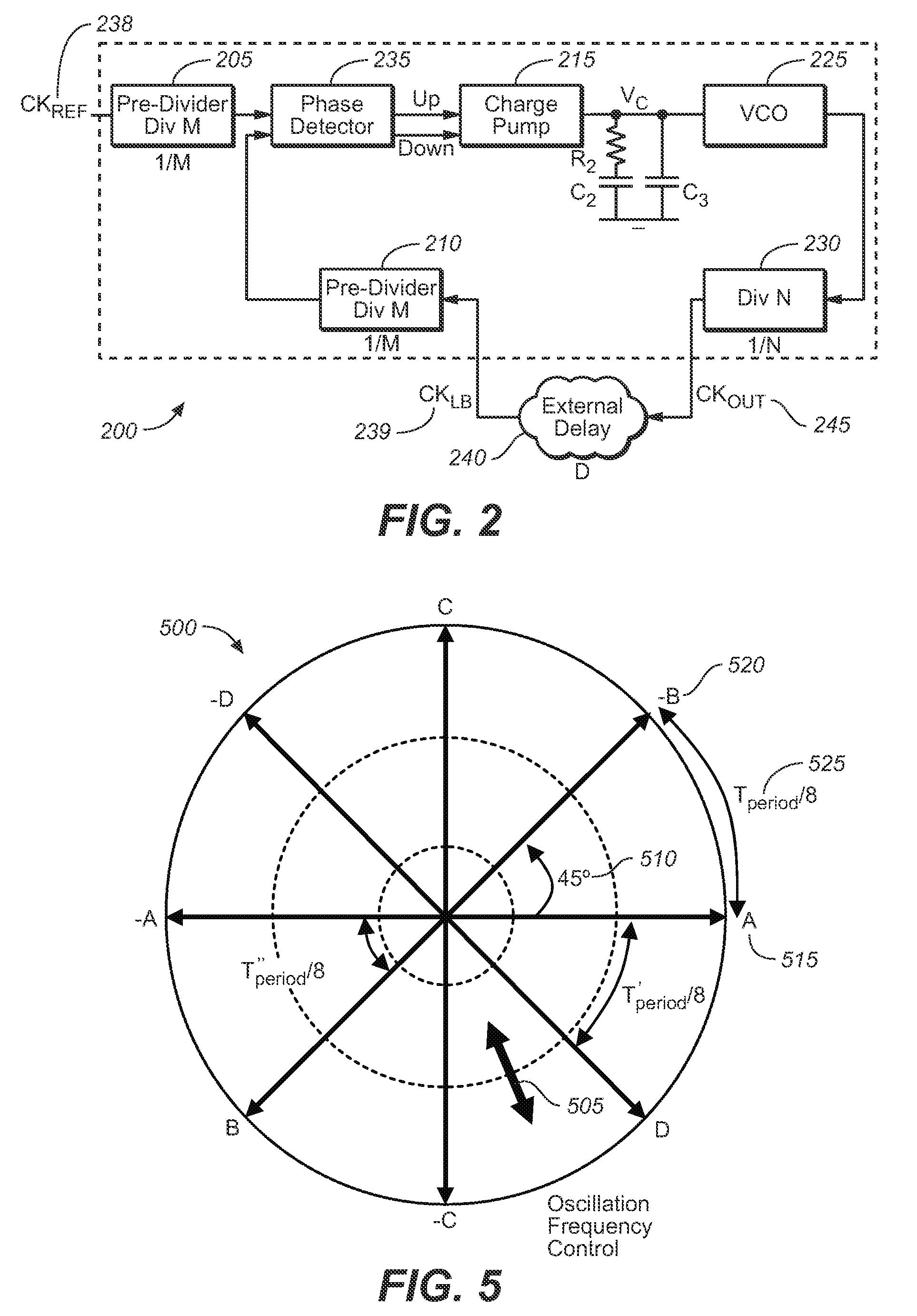
[0037]FIG. 2 depicts a block diagram of the innovative PLL of the present invention, in accordance with a preferred embodiment of the present invention. For clarity and simplicity, in FIG. 2 only single-ended connections are depicted, however other types are understood to be readily ...


PUM


Abstract

A phase-locked loop (PLL) to provide clock generation for high-speed memory interface is presented as the innovate PLL (IPLL). The IPLL architecture is able to tolerate external long loop delay without deteriorating jitter performance. The IPLL comprises in part a common mode feedback circuit with a current mode approach, so as to minimize the effects of mismatch in charge-pump circuit, for instance. The voltage-controlled oscillator (VCO) of the IPLL is designed using a mutually interpolating technique generating a 50% duty clock output, beneficial to high-speed double data rate applications. The IPLL further comprises loop filter voltages that are directly connected to each VCO cell of the IPLL. Conventional voltage-to-current (V-I) converter between loop filter and VCO is hence not required. A tight distribution of VCO gain curves is therefore obtained for the present invention across process corners and varied temperatures.

Description

FIELD OF THE INVENTION[0001]The present invention relates generally to electronics circuits, and more specifically to a digital phase-locked loop (PLL) for application in high-speed memory interfaces (HSMIs).BACKGROUND OF THE INVENTION[0002]Phase-locked loops (PLLs) are an integral part of many electronics circuits and are particularly important in communication circuits. For example, many digital systems use clock signals to trigger synchronous circuits (e.g., flip-flops). Clock signals are common in wireless devices (such as but not limited to cellular phones for example) via their digital circuitry, where the transmitter and receiver systems use local oscillator (LO) signals for frequency conversions. Typically, it is the clock and LO signals that are often generated with PLLs.[0003]Further, PLLs have a broad range of uses and applications ranging from microprocessors to memory devices (DRAM and DDR) and to clock and data recovery in a communication system, for example.[0004]As u...

Claims


Application Information

Patent Timeline
Patent Type & Authority Patents(United States)
IPC IPC(8): H03L7/00
CPCH03L1/022H03L7/0895H03L7/0998H03L7/18H03L7/0896
Inventor TAI, GWO-CHUNG
Owner MICREL
Why Eureka
Try Eureka