
High performance MOSFET

a technology of mosfet and mosfet, which is applied in the direction of semiconductor devices, basic electric elements, electrical equipment, etc., can solve the problems of reducing the channel length of a transistor, increasing the short channel effect, and reducing the device performance, so as to improve the short channel effect and improve the inverse sub-threshold slope. , the effect of improving the short channel

Inactive Publication Date: 2010-04-27
GLOBALFOUNDRIES INC
View PDF15 Cites 125 Cited by
  • Summary
  • Abstract
  • Description
  • Claims
  • Application Information

AI Technical Summary

Benefits of technology

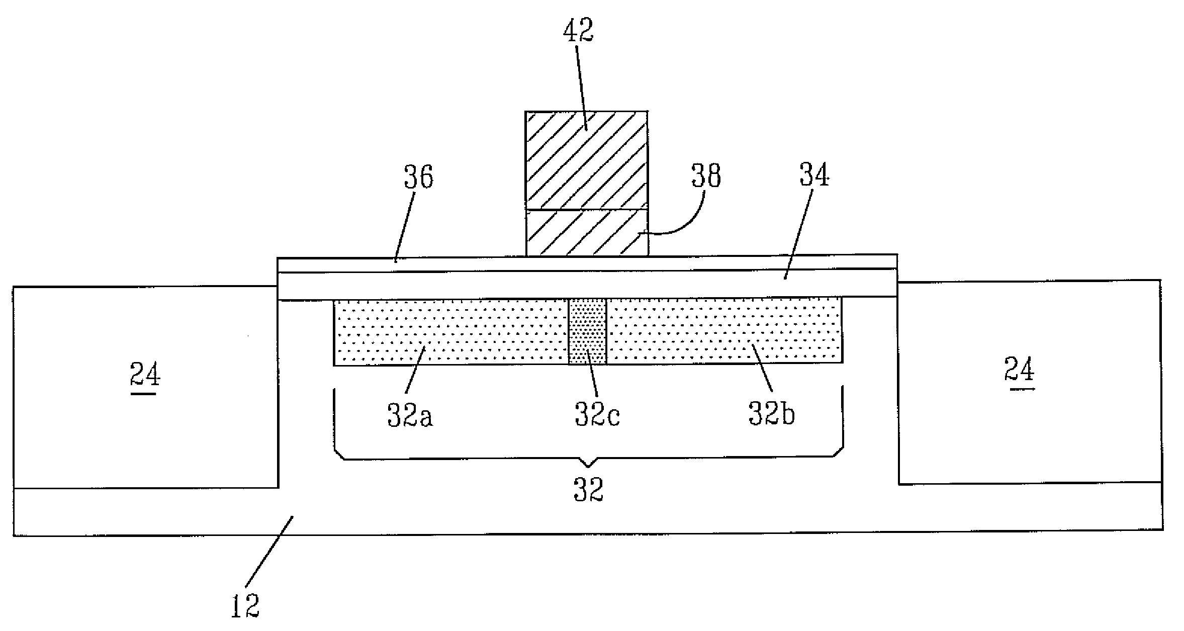
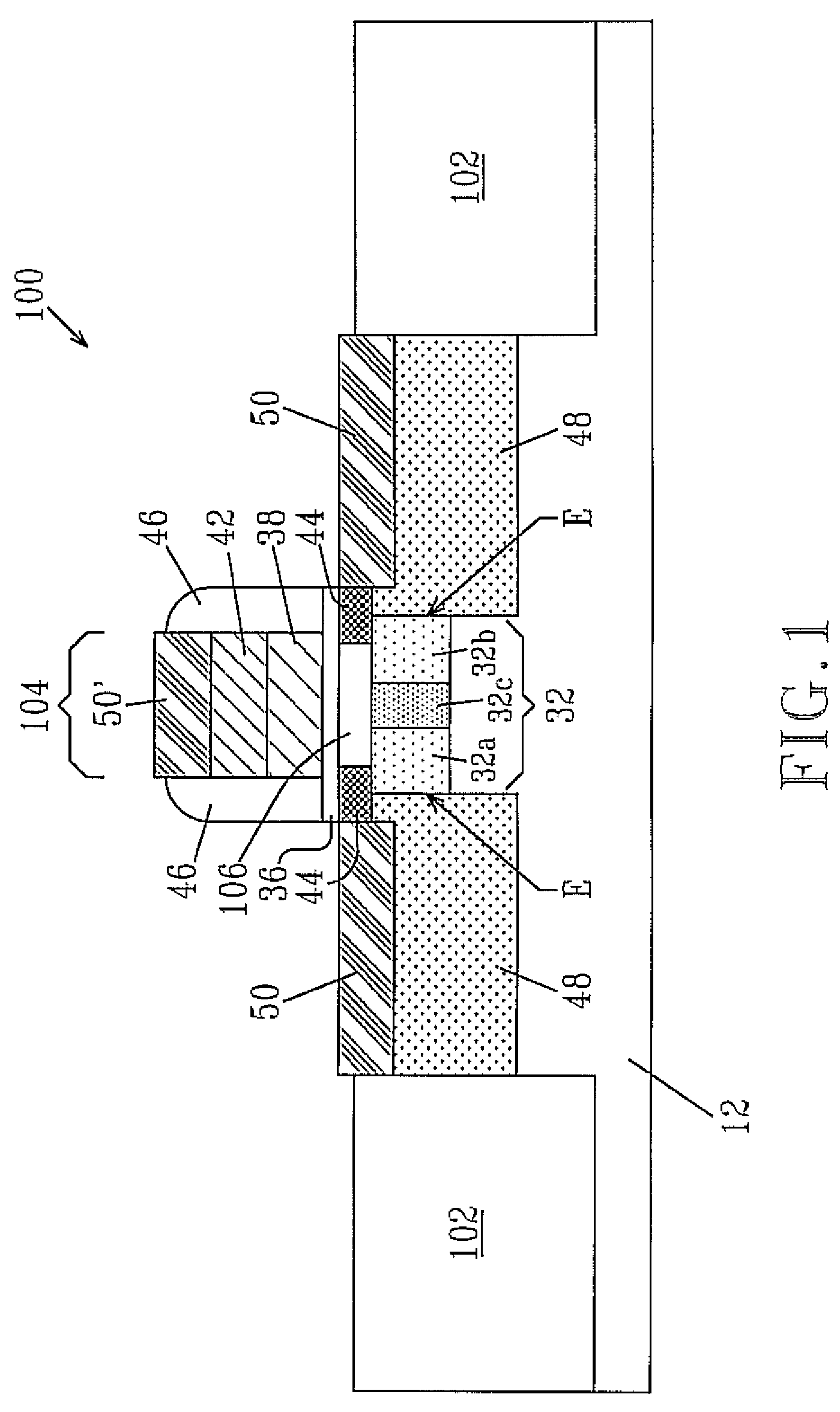
The present invention provides a semiconductor structure with improved device performance and short channel effects. The structure includes a low concentration of halo implant within an inversion layer of the structure, which enhances the control of the source / drain current. The structure also includes a well region of a first conductivity type located beneath the epitaxial semiconductor layer, which improves the short channel effects. The well region has a central portion with a higher concentration of the first conductivity type dopant than the two horizontally abutting end portions. The central portion has a higher dopant concentration than the source / drain diffusion regions of the second conductivity type. The semiconductor structure also includes source / drain extension regions and a semiconductor alloy layer. The semiconductor structure provides better performance and reliability for semiconductor devices.

Problems solved by technology

Unfortunately, reducing the channel length of a transistor also increases short channel effects, as well as “edge effects” that are relatively unimportant in long channel transistors.
In addition, one of the edge effects that may also adversely influence transistor performance is the gate-to-source / drain capacitance.
Although halo implantation can help to control short channel effects, the presence of the same in the inversion layer degrades the mobility of the carriers within the inversion layer and oftentimes reduces the device performance.
The aforementioned problems with halo implantation are increased with shorter gate lengths since a higher concentration of halo profile is typically needed.

Method used


Image

  • High performance MOSFET
  • High performance MOSFET
  • High performance MOSFET

Examples


Embodiment Construction

[0045]The present invention, which provides a semiconductor structure that exhibits high performance and improved short channel effects, and a method of fabricating the same, will now be described in greater detail by referring to the following discussion and drawings that accompany the present application. It is noted that the drawings of the present application are provided for illustrative purposes and, as such, the drawings are not drawn to scale.

[0046]In the following description, numerous specific details are set forth, such as particular structures, components, materials, dimensions, processing steps and techniques, in order to provide a thorough understanding of the present invention. However, it will be appreciated by one of ordinary skill in the art that the invention may be practiced without these specific details. In other instances, well-known structures or processing steps have not been described in detail in order to avoid obscuring the invention.

[0047]It will be unde...


PUM


Abstract

A semiconductor structure which exhibits high device performance and improved short channel effects is provided. In particular, the present invention provides a metal oxide semiconductor field effect transistor (MOFET) that includes a low dopant concentration within an inversion layer of the structure; the inversion layer is an epitaxial semiconductor layer that is formed atop a portion of the semiconductor substrate. The inventive structure also includes a well region of a first conductivity type beneath the inversion layer, wherein the well region has a central portion and two horizontally abutting end portions. The central portion has a higher concentration of a first conductivity type dopant than the two horizontally abutting end portions. Such a well region may be referred to as a non-uniform super-steep retrograde well.

Description

FIELD OF THE INVENTION[0001]The present invention relates to a semiconductor structure and a method of fabricating the same. More particularly, the present invention relates to a metal oxide semiconductor field effect transistor (MOSFET) that exhibits high performance and improved short channel effects. The inventive semiconductor structure also has an improved inverse sub-threshold slope or sub-threshold swing. In another aspect, the present invention also provides a method of fabricating such a MOSFET.BACKGROUND OF THE INVENTION[0002]Field effect transistors (FETs) are the basic building block of today's integrated circuit. Such transistors can be formed in conventional bulk substrates (such as silicon) or in semiconductor-on-insulator (SOI) substrates.[0003]State of the art metal oxide semiconductor (MOS) transistors are fabricated by depositing a gate stack material over a gate dielectric and a substrate. Generally, the MOS transistor fabrication process implements lithography a...

Claims


Application Information

Patent Timeline
Patent Type & Authority Patents(United States)
IPC IPC(8): H01L21/336H01L21/425H01L21/8238H01L21/04
CPCH01L21/26586H01L29/7833H01L29/66651
Inventor ZHU, HUILONGWANG, JING
Owner GLOBALFOUNDRIES INC
Learn More