Indoor radio transmission method for parallel radio transmission of digital data substreams and a mobile radio transmission system

a mobile radio transmission system and digital data technology, applied in the direction of polarisation/directional diversity, electromagnetic wave modulation, wireless commuication services, etc., can solve the problems of limiting the useful band or channel width of a carrier, the license frequency range cannot be accommodated, and the wireless transmission channel is not without flaws. , to achieve the effect of high transmission rate, high spectral efficiency and economical circuit structur

Inactive Publication Date: 2010-07-20
SIEMENS AG
View PDF5 Cites 25 Cited by
  • Summary
  • Abstract
  • Description
  • Claims
  • Application Information

AI Technical Summary

Benefits of technology

[0017]In the wireless transmission method the channel estimation is separated from the data transmission by the simultaneous execution of both operations. The channel matrix for recovering the original data subsignals is accurately measured in real time with the transmission thereof. In this manner, the entire available spectral efficiency is made available for the data transmission. Time gaps in the data transmission, as those present in the known BLAST method in consequence of the alternatingly executed transmission of training sequences for measuring the channel matrix, do not occur. In the method in accordance with the invention, the entire multi-path transmission channel may be utilized without interruptions for transmitting data; the data subsignals are being transmitted continuously. The channel matrix is simultaneously measured at a period adjusted to the required accuracy. The method of accurately measuring the channel matrix is based upon the introduction of an additional signal which is weak compared to the data subsignal and which is modulated with the pilot signal characteristic of each transmission antenna. A weak specially encoded and well recognizable pilot signal is superimposed on each data subsignal. At this point, it is to be mentioned that the greatest gain in spectral efficiency may be achieved by a simultaneous transmission. In individual cases, it may, however, be advantageous to transmit the pilot signal alternatingly and in time slot provided therefor, without any substantial loss of efficiency. One advantage in this connection is the somewhat more efficient generation of the pilot signals relative to the data subsignals.
[0023]In this mobile wireless transmission system, essential components of the signal processing are executed as hardware which in addition to the high spectral efficiency, also makes possible the high transmission rate. The processing network numerically weighted by means of the digital processor is realized completely by circuit technology. The utilization of simple signal generators with shift registers in accordance with an advantageous embodiment of the mobile transmission system makes possible an economical circuit structure substantially immune from interferences for measuring the channel matrix with a highly accurate signal recovery. In connection with the mobile transmission system, attention also is directed to the specific portion of the specification in order to avoid repetitions.

Problems solved by technology

Wireless transmission channels are not without flaws.
Echoes of signals at the receiver result in superimposition and interferences which limit the useful band or channel width of a carrier modulated with data to a value below the frequency range licensed to an individual offeror.
However, the licensed frequency range cannot accommodate this.
This, however, leads to a reduced sensitivity of the reception.
But the spectral limits can also not always be reached by OFDM.
However, mobile users may not easily accept the alignment procedures (tracking) required for the network connection.
This proposal for solving the problem appears not to be practicable in connection with wireless networks in indoor spaces.
Trials with digital signal processors for accommodating high data rates have failed at only a fraction of the required antenna elements.
In view of these results it does not seem possible in the foreseeable future with 10×10 antenna elements to achieve a data rate of 100 Mbit / s.
The complexity of the Butler matrix quickly increases, however, as a function of the number of outputs.
Realization of such a network would appear not to be reasonable.
However, for measuring the channel matrix and data transmission, the known method utilizes alternating time periods, so that 20% of the achievable effectiveness is lost again.
In addition, space-time processing in real time is performed with a digital signal processor which limits the data throughput to less than 1 Mbit / s.
However, in the near future it seems unlikely that such data rates will be achieved with data processing based on a digital signal processor, such as the known BLAST method.

Method used


Image

  • Indoor radio transmission method for parallel radio transmission of digital data substreams and a mobile radio transmission system
  • Indoor radio transmission method for parallel radio transmission of digital data substreams and a mobile radio transmission system
  • Indoor radio transmission method for parallel radio transmission of digital data substreams and a mobile radio transmission system

Examples


Embodiment Construction

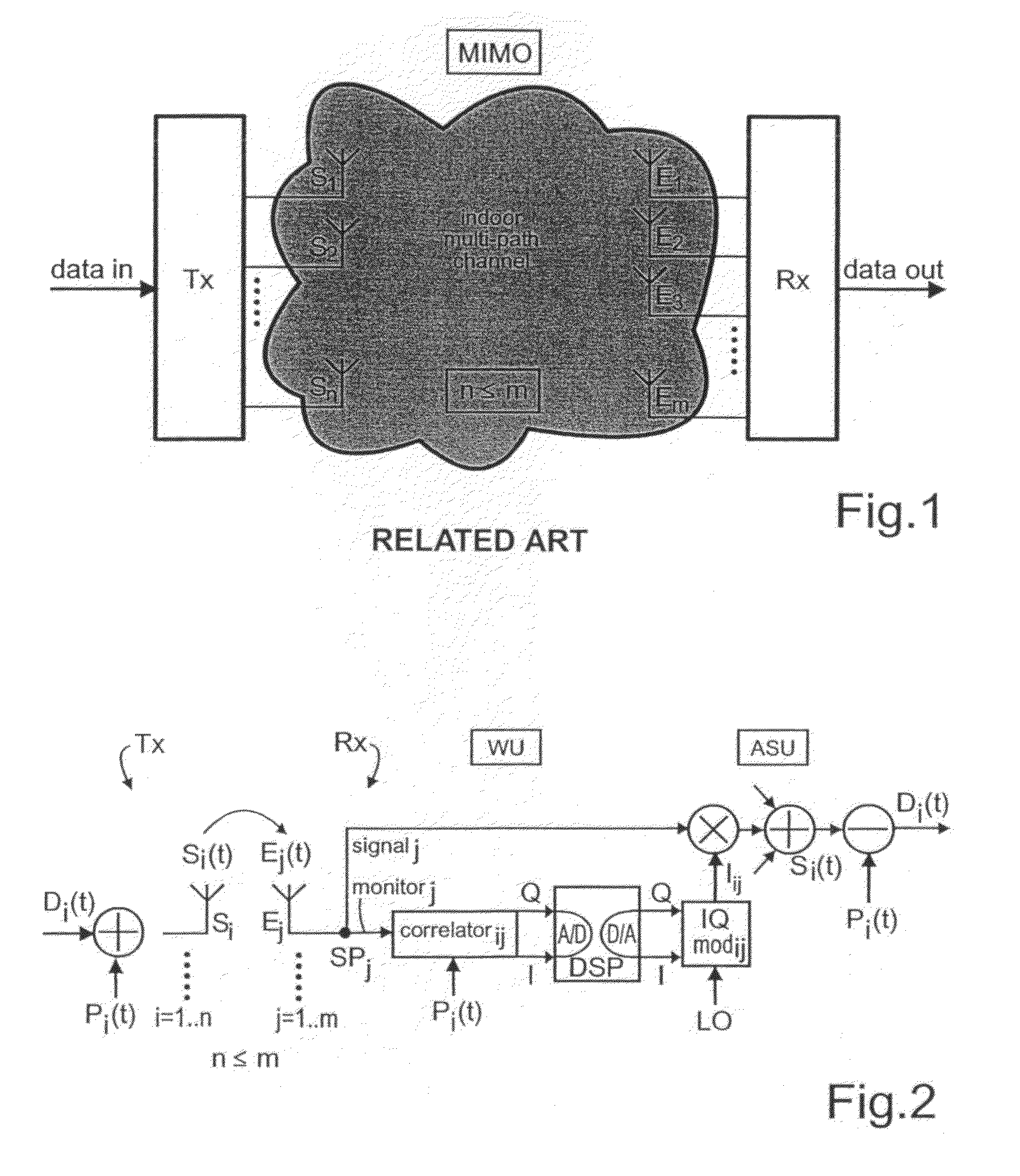
[0032]Reference will now be made in detail to the preferred embodiments of the present invention, examples of which are illustrated in the accompanying drawings, wherein like reference numerals refer to like elements throughout. FIG. 1 depicts the structure of a multiple input / multiple output system MIMO as is known from the state of the art, with the relation of a transmitter Tx at the transmission side to a receiver Rx at the receiving side over a multipath transmission channel in an indoor space.

[0033]FIG. 2 depicts the basic scheme of the transmission method and system TS in accordance with the invention which will hereafter be explained in greater detail.

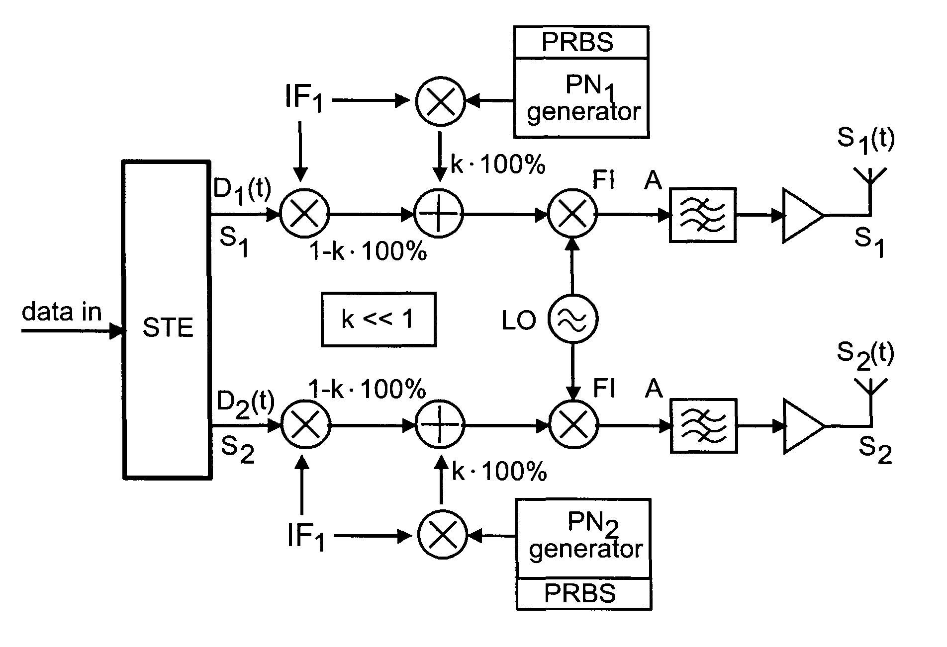
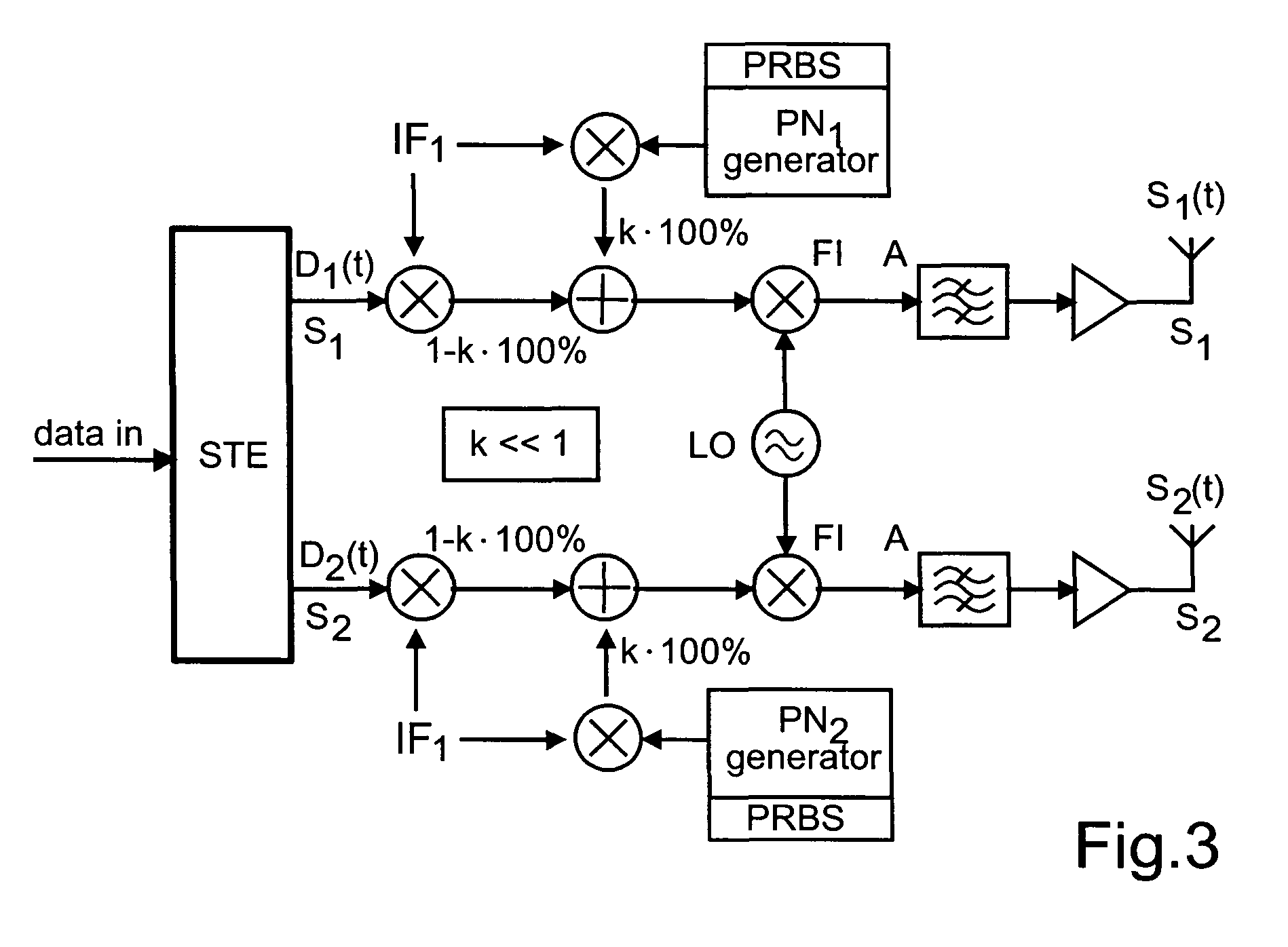
[0034]Superimposing of Pilot Sequences

[0035]The new concept of channel matrix measuring will be explained hereafter as the essential component of the wireless transmission method in accordance with the invention. Basically, a modulated weak auxiliary channel carrier is added to each transmission path. Hence, a pilot signal char...


PUM


Abstract

A radio transmission method and a wireless transmission system comprising multiple transmitter and receiver antennae simultaneously operating within the same frequency range and space-time encoders and decoders. Data transmission and channel matrix measurement can take place synchronously. Characteristic pilot signals that are unequivocally recognizable are superimposed with low noise on the data subsignals in the transmitter and are used in the receiver for the analog measurement of the channel matrix in a weighting unit and for the analog recovery of the transmitted data subsignals from the received signals. The measured analog values are digitally processed in a signal processor. The weightings thus determined are then summed in an analog signal processing unit.

Description

BACKGROUND OF THE INVENTION[0001]The invention relates to a method of indoor radio transmission for the parallel radio transmission of digital substreams formed by space-time encoding as a function of a selected data modulation format relative to a number n of data signals, in a multi-path transmission channel of limited frequency between a number of n transmission paths and a number m (m≦n) reception paths positioned at various sites within the indoor space with a measurement of the elements of the complex valued channel matrix for estimating the space-time-behavior of the transmission channel and space-time signal processing in the receiving paths while determining a weighting matrix derived from the complex valued for the simultaneous recovery of the data subsignals which by space-time encoding are again formed into digital data substreams, and to a mobile radio transmission system.[0002]Wireless transmission channels are not without flaws. Echoes of signals at the receiver resul...

Claims


Application Information

Patent Timeline
Patent Type & Authority Patents(United States)
IPC IPC(8): H04L1/02H04J99/00H04B1/06H04B7/04H04B7/0413H04B7/06H04B7/08H04L1/06H04L12/28
CPCH04B7/0413H04B7/0669H04B7/0842H04L1/0618
Inventor JUNGNICKEL, VOLKERKRUEGER, UDOPOHL, VOLKERVON HELMOLT, CLEMENSHAUSTEIN, THOMASSTANCZAK, SLAWOMIR
Owner SIEMENS AG
Why Eureka
Try Eureka