
Sidewall derivatized carbon nanotubes

a carbon nanotube and derivatization technology, applied in the field of derivatization carbon nanotubes, can solve the problems of difficult separation of individual carbon nanotubes from the other reaction products and purification, low nanotube yield, and significant variation in structure and size of tubes, etc., to achieve high electrical resistance

Inactive Publication Date: 2010-08-24
RICE UNIV
View PDF12 Cites 26 Cited by
  • Summary
  • Abstract
  • Description
  • Claims
  • Application Information

AI Technical Summary

Benefits of technology

[0014]It is another object of this invention to provide a high yield, single step method for producing large quantities of continuous macroscopic carbon fiber from single-wall carbon nanotubes using inexpensive carbon feedstocks at moderate temperatures.
[0016]This invention provides single wall carbon nanotubes and / or tubular carbon molecules derivatized with substituents covalently bonded to carbon atoms of the side wall of the nanotube or molecule. The substituents may in principle be attached on the interior and / or exterior of the nanotube side wall, but the attachment will not be predominantly on the exterior wall. In particular, the single wall carbon nanotubes may have substituents selected from fluorine, alkyl and phenyl attached to the side wall. Such single wall carbon nanotubes having fluorine covalently bonded to the side wall of the nanotube demonstrate high electrical resistance.

Problems solved by technology

While the arc discharge process can produce single-wall nanotubes, the yield of nanotubes is low and the tubes exhibit significant variations in structure and size between individual tubes in the mixture.
Individual carbon nanotubes are difficult to separate from the other reaction products and purify.
While there have been many reports and review articles on the production and physical properties of carbon nanotubes, reports on chemical manipulation of nanotubes have been slow to emerge.
While theoretical results have suggested that functionalization of the nanotube side-wall is possible (Cahill, et al., Tetrahedron, 1996, 52 (14):5247-5256), experimental evidence confirming this theory has not been obtained.

Method used


Image

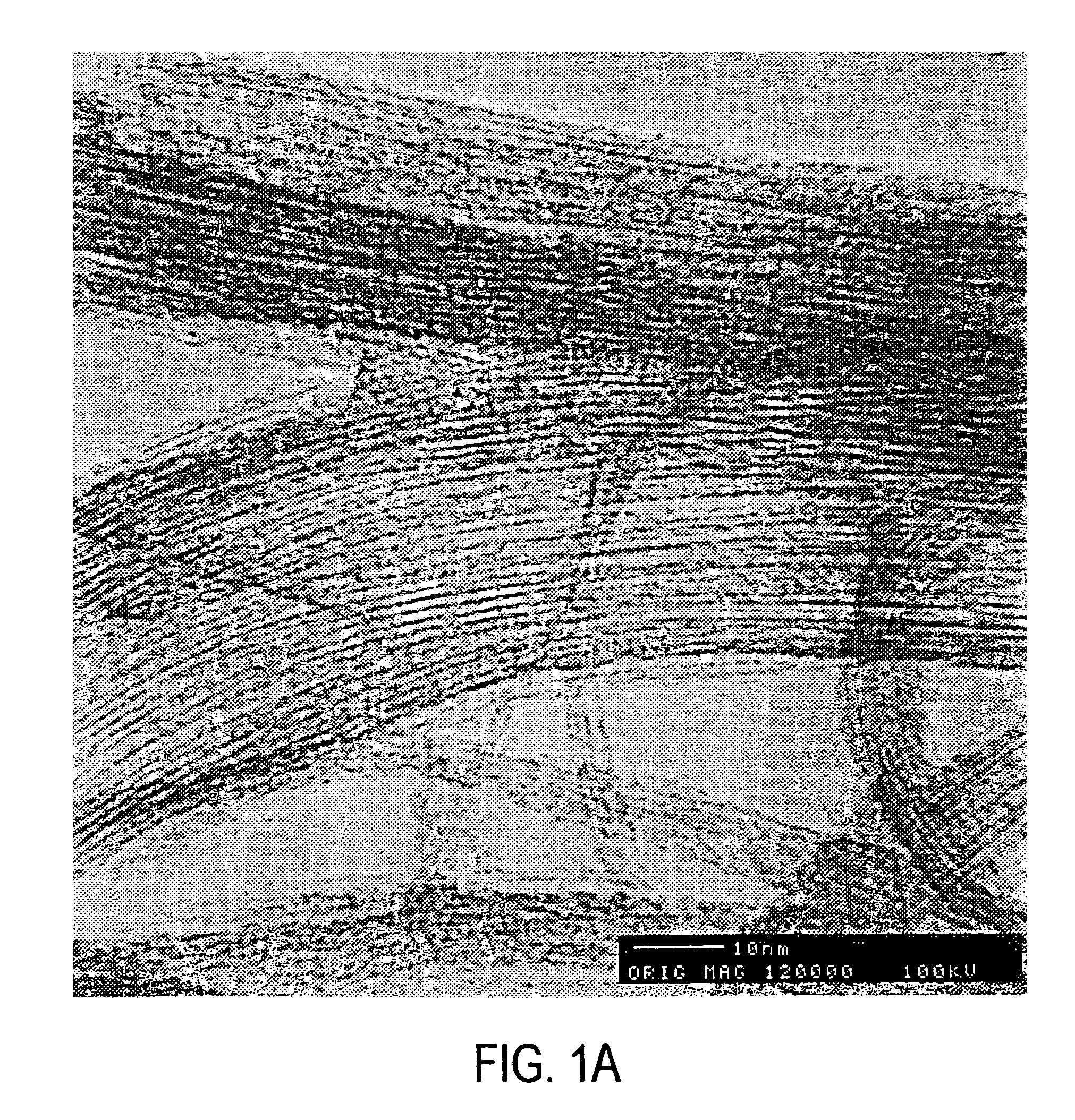
  • Sidewall derivatized carbon nanotubes
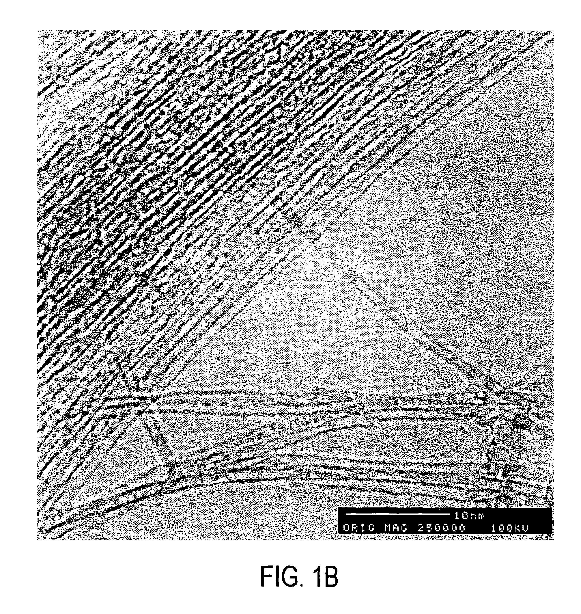
  • Sidewall derivatized carbon nanotubes
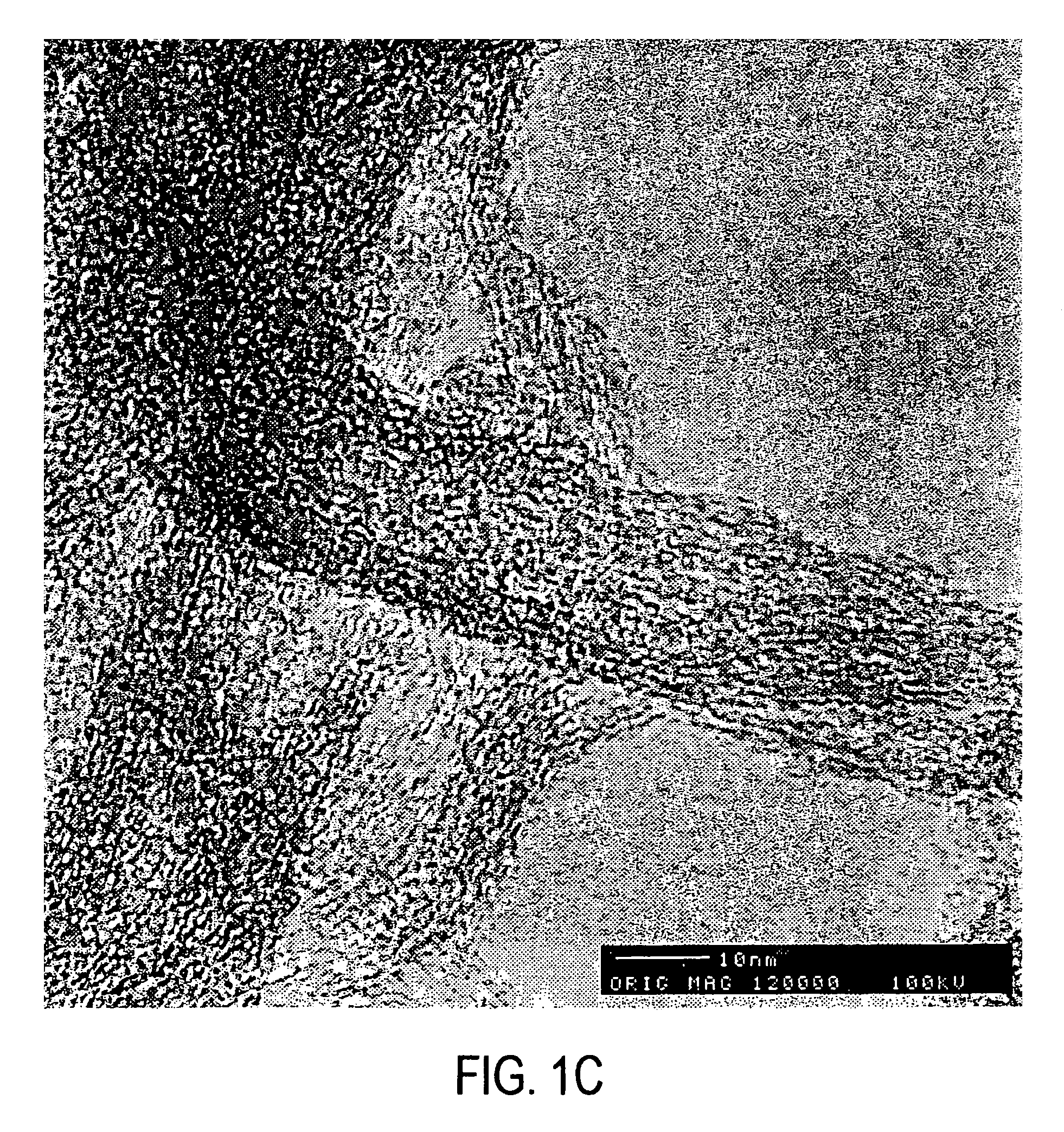
  • Sidewall derivatized carbon nanotubes

Examples


example 1

1.1 Fluorination of Single-Wall Carbon Nanotubes

[0100]Single-walled carbon nanotubes were produced by the dual pulsed laser vaporization of Co / Ni doped graphite rods and purified by techniques described previously (Rinzler, et al., 1998). The purification product is a metastable colloidal suspension of SWNT “ropes” (bundles of hexagonally close packed tubes ranging from a few to 200 SWNT, See Thess, et al., 1996) in a 0.2% aqueous solution of Triton X-100 surfactant. Filtering the solution through a PTFE filter membrane and washing with methanol to remove residual surfactant leaves a black film on the surface. If this layer is sufficiently thick (10-75 μm) it can be peeled off to form a free standing film or “bucky paper” of SWNT. This form has appreciable mechanical integrity and is convenient for handling, and for electrical conductivity and Raman scattering measurements. It is the fluorination of this “bucky paper” that is described here.

[0101]In fluorinating the SWNT, elemental ...

example 2

2.1 Preparation of Fluorinated Single-Wall Carbon Nanotubes

[0112]SWNT were produced by the dual pulsed laser vaporization of Co / Ni doped graphite rods and purified as discussed previously (Rinzler, et al., 1998). The highly purified product consists of colloidally suspended bundles or “ropes” of SWNT (Liu, et al., 1998). Filtering this over a 0.2 micron PTFE filter membrane and rinsing with methanol yields a black film that can be peeled off to give a freestanding “bucky paper.” This paper was then oven baked for several hours at 150° C. to remove any residual solvent. The baked “bucky paper” was then loaded into a temperature controlled monel flow reactor where it was purged at 250° C. under a stream of He for ˜1 hour. A 10% F2 in He mixture was then passed over the sample after first being passed over NaF to remove any HF present. This yielded material with stoichiometries ranging from C3F to C2F (as determined by electron microprobe analysis) depending on reaction time (between 8...

example 3

3.1 Preparation of Highly Purified SWNTs

[0120]Single wall carbon nanotubes were produced by the dual pulsed laser vaporization of Co / Ni doped graphite rods and purified by methods discussed previously (Rinzler, et al., Appl. Phys. A, 1998, 67:9-37). The SWNTs produced in this way are primarily (10,10) nanotubes. The purified product is a metastable colloidal suspension of SWNT “ropes” (bundles of tubes ranging from a few to 200 SWNTs, see Thess, et al., Science 1996, 273, 483-487) in a 0.2% aqueous solution of Triton™ X-100 surfactant. This was then filtered over a PTTE filter membrane (Sartorius, with 0.2 μm pore dimensions) and rinsed with methanol. Filtering this and rinsing with methanol leads to a final product which is a freestanding “mat” or “bucky paper” of SWNTs that is approximately 10 μm thick. Purity of the SWNTs was monitored via scanning electron microscopy (JEOL 6320F SEM). FIG. 9 shows a sample of typical purity. This product was then resuspended by sonication in dim...


PUM

PropertyMeasurementUnit
temperatureaaaaaaaaaa
lengthaaaaaaaaaa

Abstract

This invention is directed to chemical derivatives of carbon nanotubes wherein the carbon nanotubes have a diameter up to 3 nm. In one embodiment, this invention also provides a method for preparing carbon nanotubes having substituents attached to the side wall of the nanotube by reacting single-wall carbon nanotubes with fluorine gas and recovering fluorine derivatized carbon nanotubes, then reacting fluorine derivatized carbon nanotubes with a nucleophile. Some of the fluorine substituents are replaced by nucleophilic substitution. If desired, the remaining fluorine can be completely or partially eliminated to produce carbon nanotubes having substituents attached to the side wall of the nanotube. The substituents are dependent on the nucleophile, and preferred nucleophiles include alkyl lithium species such as methyl lithium.

Description

PRIORITY BENEFIT AND CROSS REFERENCE TO RELATED APPLICATIONS[0001]This Application is a divisional application of U.S. Ser. No. 09 / 809,885, “CHEMICAL DERIVATIZATION OF SINGLE-WALL CARBON NANOTUBES TO FACILITATE SOLVATION THEREOF; AND USE OF DERIVATIZED NANOTUBES TO FORM CATALYST-CONTAINING SEED MATERIALS FOR USE IN MAKING CARBON FIBERS” to Margraves et al., filed Mar. 16, 2001, which is a divisional application of U.S. patent application Ser. No. 09 / 787,473, filed Mar. 16, 2001 (issued as U.S. Pat. No. 6,835,366, Dec. 28, 2004), which is the 35 U.S.C. §371 national application of International Application Number 99 / 21366, filed September 1999, which designated the United States and claimed priority benefits to U.S. Patent Application Nos. (1) 60 / 101,092, filed Sep. 18, 1998; (2) 60 / 106,918 filed Nov. 3, 1998; and (3) 60 / 138,505, filed Jun. 10, 1999.[0002]The present invention is also related to the following United States Patent Applications, all of which are divisionals (directly o...

Claims


Application Information

Patent Timeline
Patent Type & Authority Patents(United States)
IPC IPC(8): B82B1/00B01J21/18B01J23/74B01J23/755B01J35/06C01B31/02D01F11/12
CPCB01J21/18B01J35/06B82Y40/00C01B31/0273D01F11/121B01J23/74Y10S977/74B01J23/755B01J35/006B82Y30/00C01B2202/02C01B2202/06Y10S977/75Y10S977/843Y10S977/748Y10S977/848C01B32/174B01J35/393B01J35/58
Inventor MARGRAVE, JOHN L.MICKELSON, EDWARD T.HAUGE, ROBERTBOUL, PETERHUFFMAN, CHADLIU, JIESMALLEY, RICHARD E.SMITH, KENCOLBERT, DANIEL T.
Owner RICE UNIV
Learn More