
Method of manufacturing carbon nanostructure

a carbon nanotube and manufacturing method technology, applied in the direction of physical/chemical process catalysts, metal/metal-oxide/metal-hydroxide catalysts, crystal growth processes, etc., can solve the problems of difficult control of the shape of the catalyst particles, difficult to manufacture uniform carbon nanotubes in a stable manner, and cause variation in morphology. , to achieve the effect of uniform shape, high purity and stable manner

Active Publication Date: 2010-08-31
SUMITOMO ELECTRIC IND LTD
View PDF21 Cites 58 Cited by
  • Summary
  • Abstract
  • Description
  • Claims
  • Application Information

AI Technical Summary

Benefits of technology

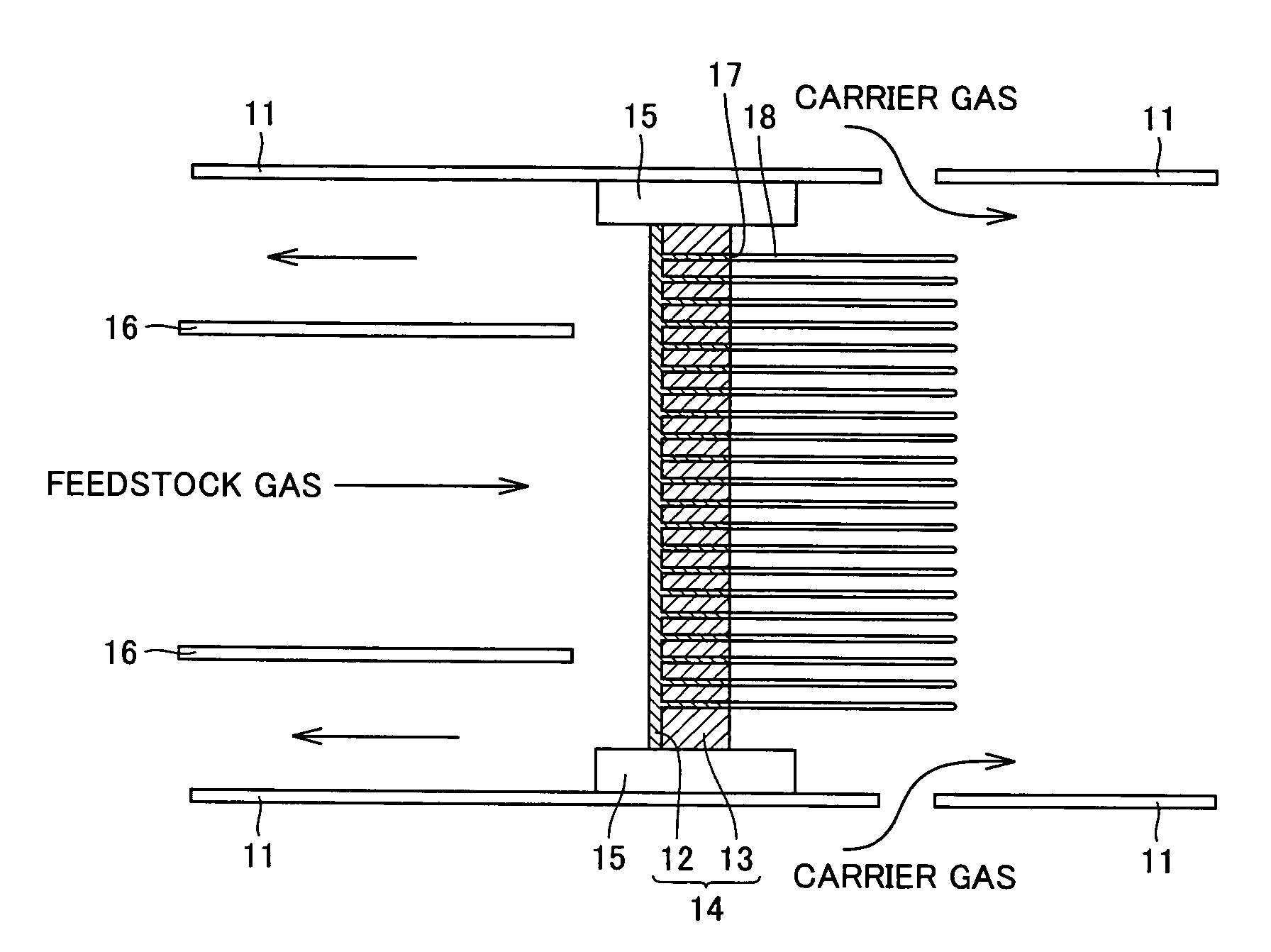
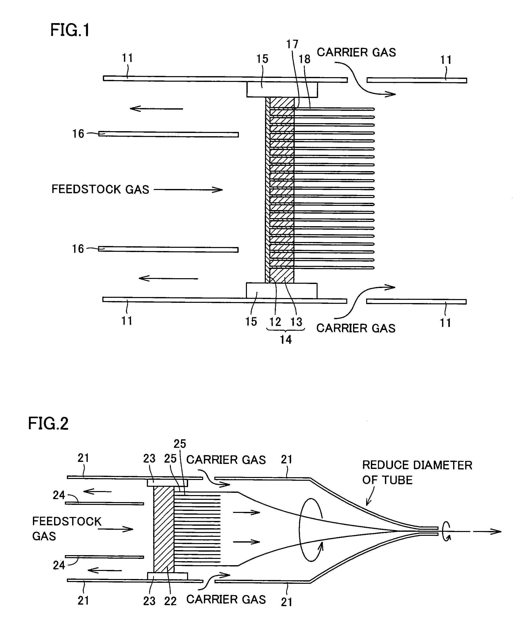
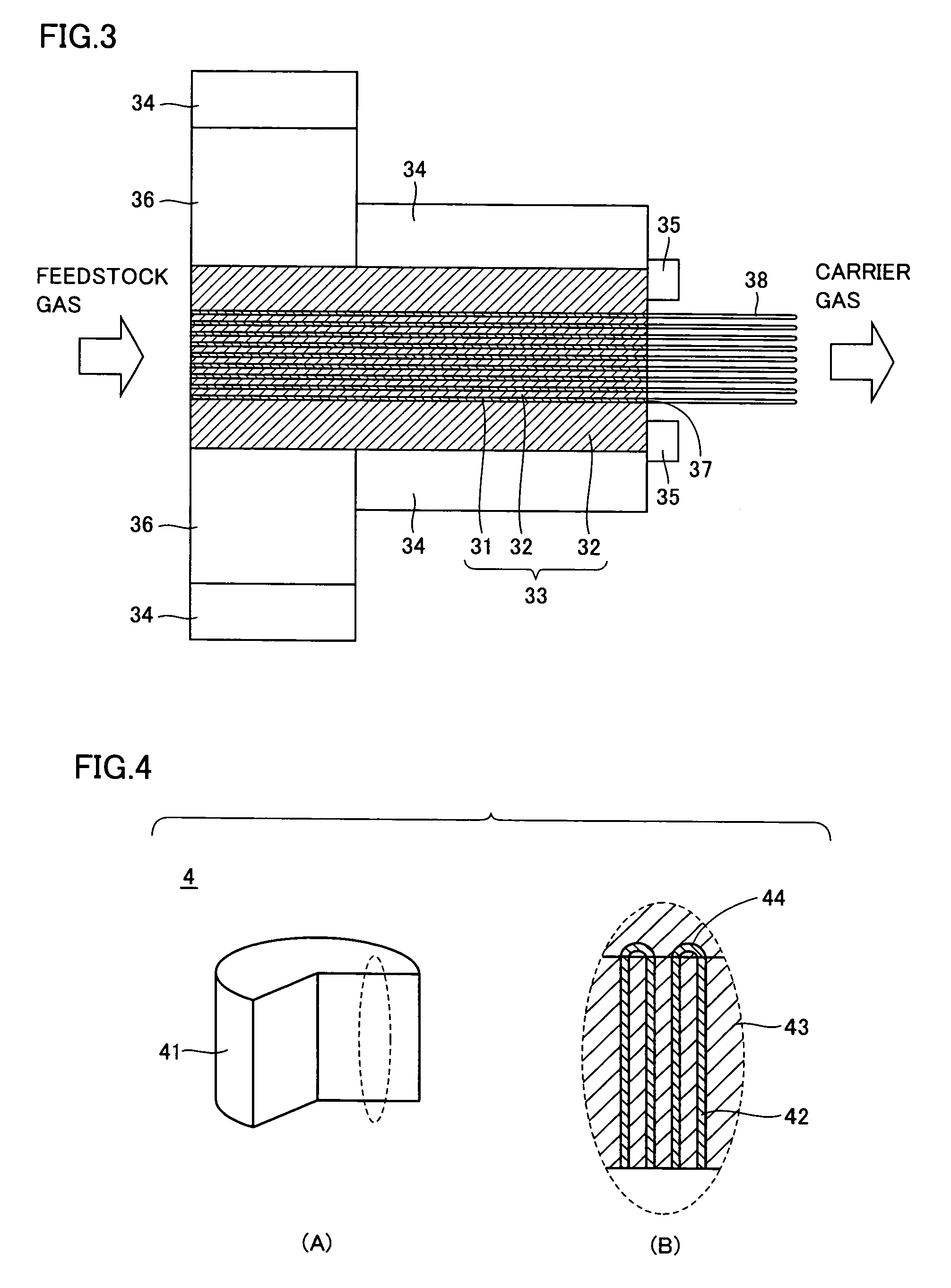
The present invention provides a method for manufacturing carbon nanostructures with a uniform shape, high purity, and stability. By controlling the conditions for bringing an ambient gas into contact with a catalytic base, and the pressure and temperature, carbon nanostructures can be produced in a continuous and stable manner. The method allows for the growth of crystalline carbon on a catalytic base using a combination of a catalytic material and a non-catalytic material. The non-catalytic material can be selected from a variety of materials, such as Ag, Au, and Pt. The method also includes steps for setting the ambient gas to be brought into contact with the catalytic base with different pressures and forming a reinforce material to suppress deformation of the catalytic base. The invention allows for the manufacturing of carbon nanostructures with a uniform shape, high purity, and stability.

Problems solved by technology

Unfortunately, conventional methods such as those in Patent Documents 1 to 4 produced carbon-containing by-products such as amorphous carbon or graphite in addition to desired carbon nanotubes.
They also produced carbon nanotubes with large variation in their diameter, making it difficult to manufacture uniform carbon nanotubes in a stable manner.
Since it is difficult to control the shape of the catalyst particles when they are formed by means of a chemical method such as the pyrolysis method, variation in their morphology is caused.
Further, varying growth rate of crystalline carbon on catalyst particles as well as simultaneous occurrence of dissolution and precipitation of the carbon grown by pyrolysis of a feedstock gas on the same surface also tend to cause the variation among the resulting carbon nanotubes in their shape.

Method used


Image

  • Method of manufacturing carbon nanostructure
  • Method of manufacturing carbon nanostructure
  • Method of manufacturing carbon nanostructure

Examples


example 1

[0096](1) Fabrication of Catalytic Base

[0097]An Fe (iron) pipe with an outer diameter of 40 mm and an inner diameter of 30 mm was inserted into an Ag (silver) pipe with an outer diameter of 60 mm and an inner diameter of 40 mm, and an Ag rod with an outer diameter of 30 mm was inserted into the Fe pipe. The combined metal material underwent wiredrawing until it had an outer diameter of 1.2 mm to provide a wire 1.

[0098]Wire 1 was cut into segments each with a length of 1 meter which were then bundled together, with which an Ag pipe with an outer diameter of 60 mm and an inner diameter of 50 mm was filled. The resulting material underwent wiredrawing until it had an outer diameter of 1.2 mm to provide a wire 2.

[0099]The step of producing wire 2 from wire 1 was repeated to ultimately provide an assembly that has a diameter of about 12 mm and that is made of a plurality of catalyst structures bundled together having Fe with an outer diameter of about 8 nm and an inner diameter of about ...

example 2

[0108](1) Fabrication of Catalytic Base

[0109]An Fe—Co (iron-cobalt) alloy pipe with an outer diameter of 50 mm and an inner diameter of 40 mm was inserted into a Ag—Pd (silver-palladium) alloy pipe with an outer diameter of 60 mm and an inner diameter of 50 mm, and an Ag—Pd alloy rod with an outer diameter of about 40 mm was inserted into the Fe—Co alloy pipe. The combined metal material underwent wiredrawing until it had an outer diameter of 1.2 mm to provide a wire 1.

[0110]Wire 1 was cut into segments each with a length of 1 meter which were then bundled together, with which an Ag—Pd alloy pipe with an outer diameter of 60 mm and an inner diameter of 50 mm was filled. The resulting material underwent wiredrawing until it had an outer diameter of 1.2 mm to provide a wire 2.

[0111]The step of producing wire 2 from wire 1 was repeated to ultimately provide an assembly that has a diameter of about 12 mm and that is made of a plurality of catalyst structures bundled together having Fe—C...

example 3

[0121](1) Fabrication of Catalytic Base

[0122]An Fe—Co—Mo (iron-cobalt-molybdenum) alloy pipe with an outer diameter of 30 mm and an inner diameter of 20 mm was inserted into an Ag (silver) pipe with an outer diameter of 50 mm and an inner diameter of 30 mm, and an Ag pipe with an outer diameter of about 20 mm was inserted into the Fe—Co—Mo alloy pipe. The combined metal material underwent wiredrawing until it had an outer diameter of 1.2 mm to provide a wire 1.

[0123]Wire 1 was cut into segments each with a length of 1 meter which were then bundled together, with which an Ag pipe with an outer diameter of 50 mm and an inner diameter of 40 mm was filled. The resulting material underwent wiredrawing until it had an outer diameter of 1.2 mm to provide a wire 2. The step of producing wire 2 from wire 1 was repeated to ultimately provide an assembly that has a diameter of about 12 mm and that is made of a plurality of catalyst structures bundled together having Fe—Co—Mo with an outer diam...


PUM

PropertyMeasurementUnit
temperatureaaaaaaaaaa
outer diameteraaaaaaaaaa

Abstract

The present invention relates to a method of manufacturing a carbon nanostructure for growing crystalline carbon by vapor deposition from a crystal growth surface of a catalytic base including a catalytic material, and in particular, to a method of manufacturing a carbon nanostructure where at least two gases including a feedstock gas are brought into contact with the catalytic base simultaneously. Preferably, the at least two gases are constituted by at least one feedstock gas and at least one carrier gas. Preferably, the carrier gas is brought into contact with the crystal growth surface, and the feedstock gas is brought into contact with at least a part of a region except for the crystal growth surface with which the carrier gas has been brought into contact. Preferably, the material gas contains an ion, and further preferably, it contains a carbon ion.

Description

RELATED APPLICATIONS[0001]This application is the U.S. National Phase under 35 U.S.C. §371 of International Application No. PCT / JP2005 / 001259 filed on Jan. 28, 2005, which in turn claims the benefit of JP 2004-128231 and JP 2004-220432 filed on Apr. 23, 2004 and Jul. 28, 2004 respectively.TECHNICAL FIELD[0002]The present invention relates to a method of manufacturing carbon nanostructures that allows carbon nanostructures having a uniform shape to be produced in high purity and in a stable manner.BACKGROUND ART[0003]In recent years, a carbon nanostructure, which is represented by a carbon nanotube or the like and which is formed by carbon atoms being aligned in a diameter of nanometer level, is receiving widespread attention as a carbon-base high performance material having excellent conductivity, mechanical strength and the like. As a method of producing the carbon nanotube, a pyrolysis method has been devised, where a feedstock gas such as an alcohol base gas, a hydrocarbon base g...

Claims


Application Information

Patent Timeline
Patent Type & Authority Patents(United States)
IPC IPC(8): D01F9/12D01F9/127C09C1/56C23C16/00B01J23/89B82B3/00C01B31/02
CPCB01J23/8906B01J23/8913B01J23/8993B01J35/06B82Y40/00C01B31/0233C30B25/02C30B29/02B82Y30/00Y10S977/742C01B32/162B01J35/58C01B2202/30
Inventor HIKATA, TAKESHI
Owner SUMITOMO ELECTRIC IND LTD
Learn More