Reaction vessel and process for its use

a technology of reaction vessel and reaction process, which is applied in the direction of liquid chemical process, gas-gas reaction process, liquid-gas reaction of thin-film type, etc., can solve the problems of affecting the further development of such plants, consuming energy for synthesis and treatment of starting gas mixture, and requiring apparatus and machinery

Inactive Publication Date: 2010-11-16
EVONIK DEGUSSA GMBH
View PDF10 Cites 8 Cited by
  • Summary
  • Abstract
  • Description
  • Claims
  • Application Information

AI Technical Summary

Benefits of technology

[0012]It is an object of the invention to provide a reaction vessel and a process for the preparation of hydrogen sulphide from sulphur and hydrogen at pressures of >5 bar without severe corrosion of pressure-bearing parts occurring as a result of high temperatures.
[0015]In the context of the preparation of hydrogen sulphide, the internals increase the residence time, in particular of the hydrogen in the liquid sulphur. The gaseous reactant or reactants is / are at least partly collected in these internals and subsequently become dispersed again in the liquid sulphur, if they have not been converted into hydrogen sulphide.
[0017]Reactor concepts which help avoid high overtemperatures on pressure-bearing parts have now been found for such exothermic syntheses at elevated pressure. At the same time, local overtemperatures in the region of the internals are utilized in a targeted manner to make rapid and complete reaction of the hydrogen with a high space-time yield possible. In addition, this reactor concept allows the heat of reaction to be utilized for heating and vaporization of the starting materials, here sulphur. In this way, the starting materials themselves can be utilized for heat integration.
[0018]As a result of the inventive arrangement of non-pressure-bearing internals, the sulphur-saturated hydrogen which is finely dispersed in the liquid sulphur phase is collected again there as contiguous gas phase. The residence time of the gaseous reactants in these gas collection regions or gas capture structures is significantly increased, i.e. by a factor of from about 3 to 20, in particular 5 to 15, compared to the residence time of ascending gas bubbles in reactors without internals. If the residence time of the hydrogen in the liquid sulphur is too short, hydrogen enriched with gaseous sulphur collects in the region above the liquid sulphur in the reactor and reacts to form hydrogen sulphide. It follows from this that reaction vessels without the internals according to the invention become heated strongly above the liquid sulphur by the heat liberated since the energy cannot be removed satisfactorily. According to the invention, no reaction mixture enters the space above the liquid sulphur because of the increased residence time in the region of the reactor which is filled with liquid sulphur. According to the invention, the heat liberated therefore leads to an increase in temperature to above 450° C. only within the gas collection regions or gas capture structure where the increased temperature promotes the reaction and the vaporization of sulphur. Due to the local limitation of the reaction and thus the overtemperatures which arise in the region of the internals, the entire pressure-bearing reaction vessel and in particular the region above the liquid sulphur is not heated to temperatures of >450° C. and damage to the material caused by these elevated temperatures is thus avoided. According to the invention, the collection and dispersion of the gas phase within a reaction vessel can occur once or preferably more than once as a result of the arrangement of the internals. In particular, from 3 to 100, preferably from 3 to 50, gas collection regions are arranged above one another. Gas distributors can be installed in between.
[0019]The residence time of the gaseous reactants hydrogen and sulphur, in particular of hydrogen, in an internal acting as gas collection region or gas capture region is preferably from >0.5 s to 60 s, particularly preferably from 2 to 60 s, in particular from 3 to 30 s. The temperatures prevailing in the gas collection regions or the internals can be more than 550° C. These temperatures would not be tolerable for the pressure-bearing outer wall for corrosion and safety reasons. If a plurality of gas capture structures are arranged in a reaction vessel, they are preferably arranged in the flow direction of the ascending hydrogen. The size of the gas collection or gas capture volumes of the individual internals can increase, decrease or remain constant. Preference is given to an increase in the collection volumes in the flow direction in order to compensate for the reaction time which slows with the reduction in, for example, the hydrogen concentration in the hydrogen / sulphur gas mixture by an increased residence time.

Problems solved by technology

The article by B. Glaser, M. Schütze, F. Vollhardt on “Auswertung von Daten zum H2S-Angriff auf Stähle bei verschiedenen Temperaturen und Konzentrationen”, Werkstoffe und Korrosion 42, 374-376, 1991, states that in the case of plants in which corrosive attack by H2S is to be feared at elevated temperatures, this is significantly hindering the further development of such plants.
Here, major cost factors are, in particular, the outlay for apparatuses and machinery and also the energy consumption for the synthesis and treatment of the starting gas mixture.
For example, operation of compressors and of heating and cooling circuits consumes a large amount of electric power.

Method used


Image

  • Reaction vessel and process for its use
  • Reaction vessel and process for its use

Examples


example 1

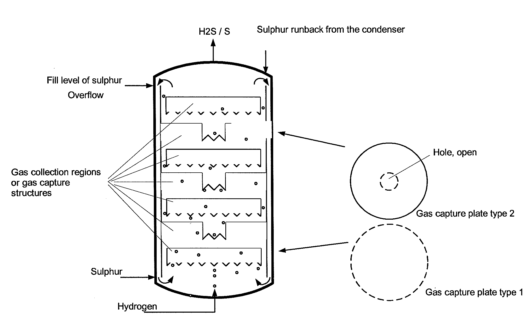
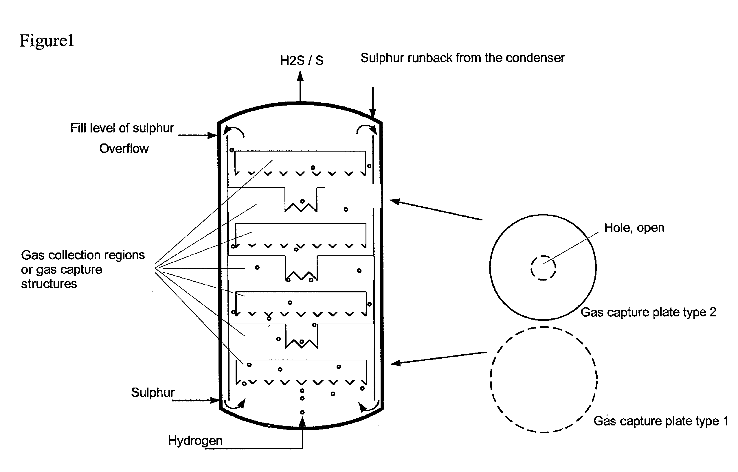
[0039]Comparative example 2 was repeated with three gas collection regions in the form of upturned cups being installed in the region of the liquid sulphur. There, the ascending gas was collected with a residence time in the range of 10-50 s. The temperature measured above the liquid sulphur was the same as that in the liquid sulphur. No overheating was observed. Furthermore, no corrosion phenomena could be discerned on the steel samples above the liquid sulphur. The conversion of hydrogen in the product gas was determined by means of GC analysis and found to be >60% (at a sulphur temperature of 400° C., analogous to the comparative example), >90% at 420° C. and >96% at 440° C.

example 2

[0040]Comparative example 2 was repeated with a bed of ceramic packing elements having an external diameter of 5 mm and a gap volume of the pellets of 70% being installed in the region of the liquid sulphur. The value of the maximum temperature above the liquid sulphur was only 5° C. above the set sulphur temperature of 397° C. Furthermore, no corrosion phenomena could be discerned on the steel samples above the sulphur. The conversion of hydrogen in the product gas was determined by means of GC analysis and found to be >99%.

[0041]The examples show that, as a result of the invention, the strongly exothermic reaction is complete within the region of the internals or gas collection regions filled with liquid sulphur and does not occur in the gas region above the liquid sulphur. As a result, no corrosion due to high overtemperatures occurs there. The hydrogen sulphide formed is of high purity.


PUM

PropertyMeasurementUnit
residence timeaaaaaaaaaa
temperatureaaaaaaaaaa

Abstract

The invention relates to a reaction vessel in which hydrogen sulphide is prepared from sulphur and hydrogen, wherein the reaction vessel consists partly or entirely of a material which is resistant to the reaction mixture, its compounds or elements and retains its resistance even at high temperatures.

Description

INTRODUCTION AND BACKGROUND[0001]The invention relates to a reaction vessel suitable for carrying out an exothermic reaction of a liquid reactant with a gaseous reactant to form a gaseous reaction product at elevated temperature and elevated pressure, wherein the residence time of the gaseous reactant in the reaction vessel is increased by non-pressure-bearing internals.[0002]Such a reaction vessel is preferably used for preparing hydrogen sulphide from sulphur and hydrogen. The reaction vessel contains internals which increase the residence time of the hydrogen in the liquid sulphur, with the gas being collected in parts of these internals and subsequently being dispersed again in the liquid sulphur.[0003]Hydrogen sulphide in particular is an industrially important intermediate, for example for the synthesis of methyl mercaptan, dimethyl sulphide, dimethyl disulphide, sulphonic acids, dimethyl sulphoxide, dimethyl sulphone and for numerous sulphiding reactions. It is nowadays obtai...

Claims


Application Information

Patent Timeline
Patent Type & Authority Patents(United States)
IPC IPC(8): B01J10/00C01B17/16
CPCB01J8/025B01J10/005B01J19/246C01B17/162
Inventor REDLINGSHOFER, HUBERTBARTH, JAN-OLAFFINKELDEI, CASPAR-HEINRICHHASSELBACH, HANS JOACHIMKRETZ, STEPHANHEINZEL, HARALDWECKBECKER, CHRISTOPH
Owner EVONIK DEGUSSA GMBH
Why Eureka
Try Eureka