Method for producing bio-fuel that integrates heat from carbon-carbon bond-forming reactions to drive biomass gasification reactions
a technology of carbon-carbon bonding and biofuel, which is applied in the direction of waste based fuel, bulk chemical production, halogenated hydrocarbon preparation, etc., to achieve the effects of improving economics, reducing capital costs, and increasing thermal efficiency of reactions
- Summary
- Abstract
- Description
- Claims
- Application Information
AI Technical Summary
Benefits of technology
Problems solved by technology
Method used
Image
Examples
example 1
Catalyst Preparation and Characterization
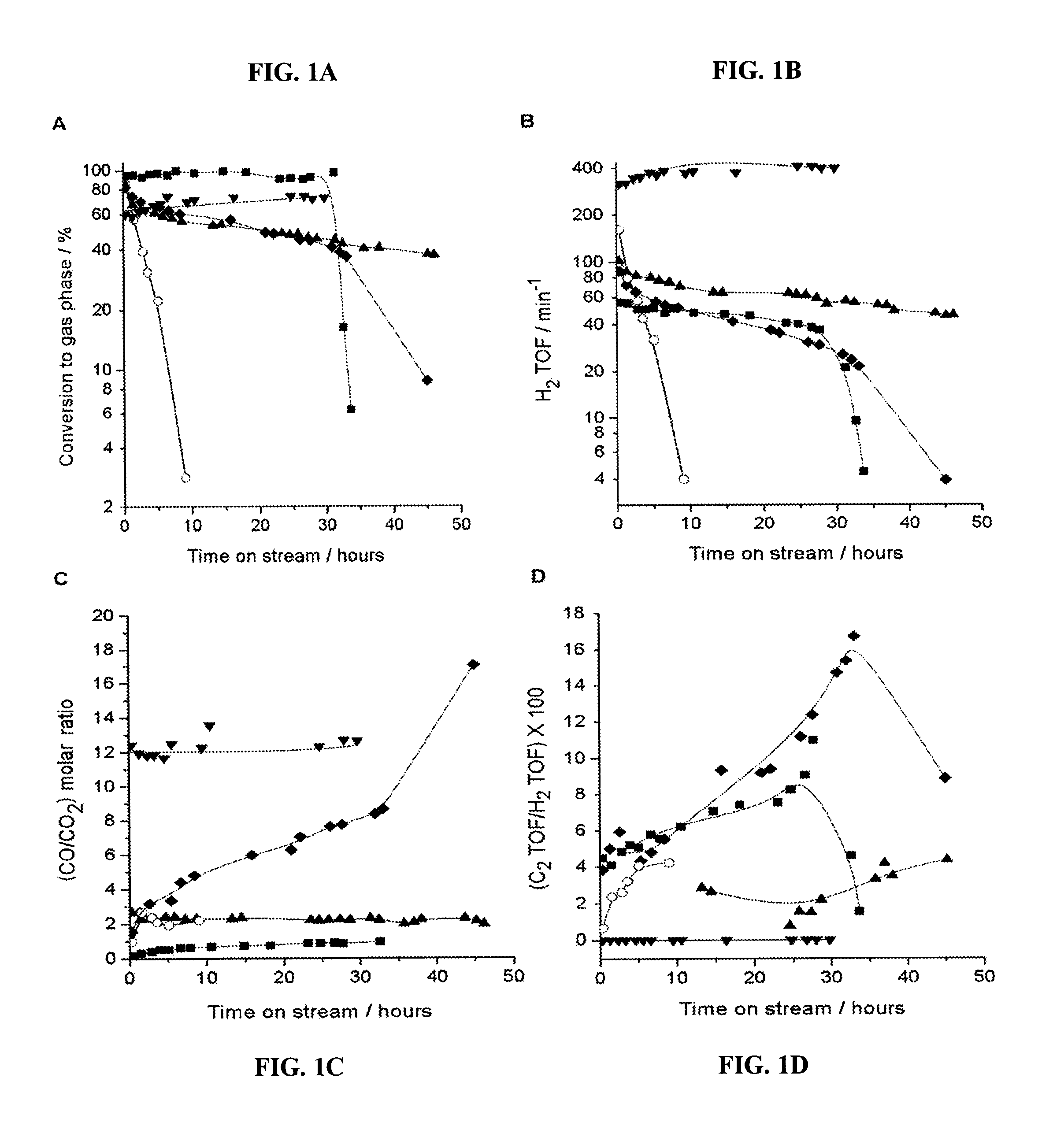
[0097]Supported Pt catalysts were prepared by incipient wetness impregnation of Al2O3 (Catapal B-brand, from Sasol, Johannesburg, South Africa and Houston, Tex.), CeO2 / ZrO2, MgO / ZrO2, and ZrO2 using chloroplatinic acid hexahydrate (Strem Chemicals, Newburyport, Mass.) for ZrO2 and CeO2 / ZrO2, and using tetraamine platinum (II) nitrate (Strem Chemicals) for Al2O3 and MgO / ZrO2. Following impregnation, the Pt / ZrO2 and Pt / CeO2 / ZrO2 catalysts were dried in air at 393 K for 15 h and calcined at 773 K for 4 h in a muffle furnace. During calcination, the temperature was increased from room temperature to 373 K and held for 1 hour, then increased by increments of 100 K to 773 K, holding at each increment for 1 hour. The MgO / ZrO2-and Al2O3-supported Pt catalysts were dried in air for 15 hours at 393 K and then calcined in flowing O2 / He gas mixtures (20% for Pt / MgO / ZrO2 and 10% for Pt / Al2O3, using a flow rate of 300 cm3 (NTP) per minute) to 533 K (at 1.3...
example 2
Reaction Kinetics Measurements
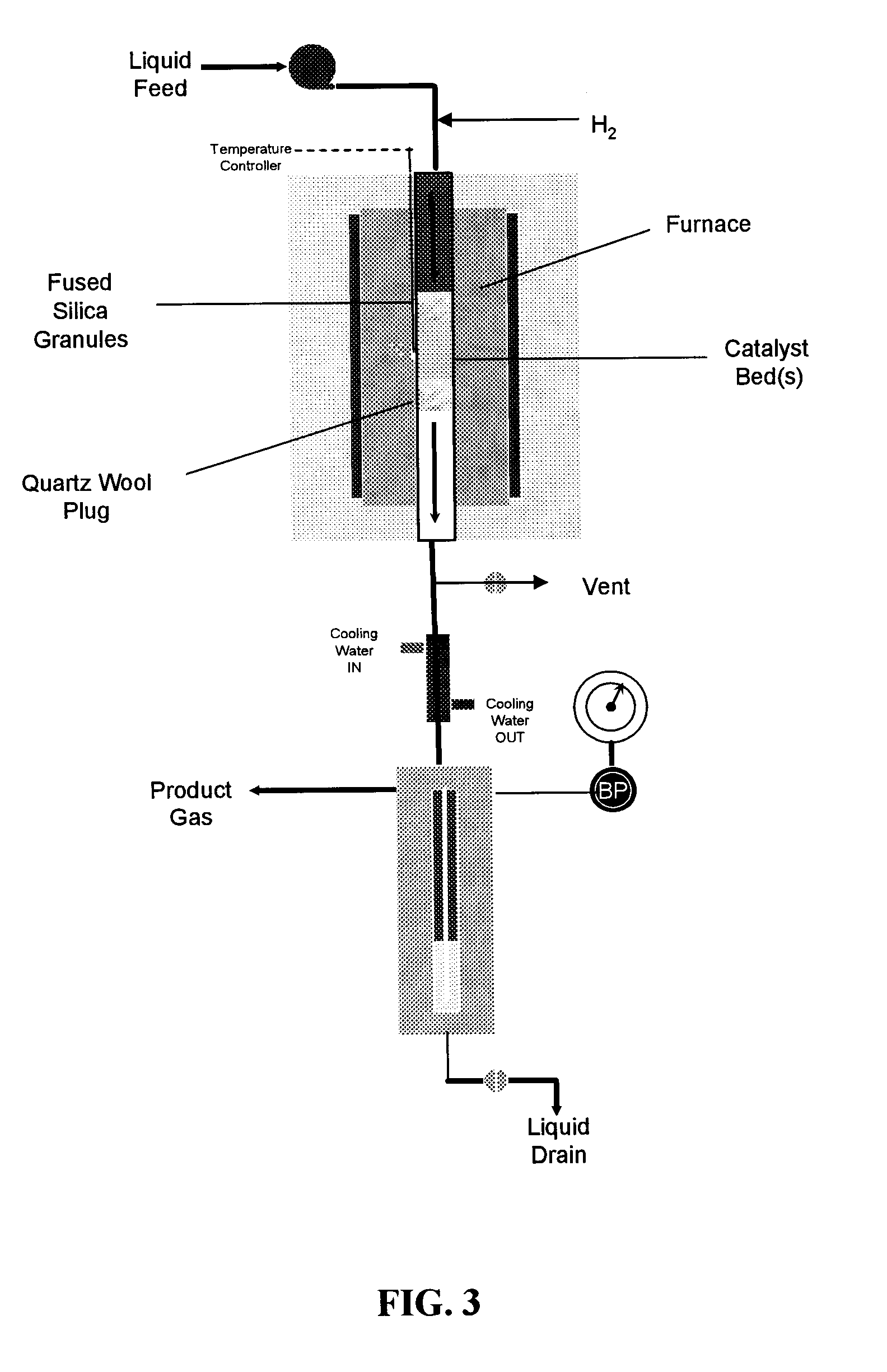
[0101]FIG. 3 shows a schematic of the apparatus used to conduct reaction kinetics measurements. A shown in the figure, the apparatus comprises a tubular reactor disposed within a furnace. Fused silica granules and quartz wool are used to hold one or more catalyst beds within the reactor. The effluent from the tubular reactor is passed through a cooling column, and the product gases are separated from the product liquids. Both the product gases and liquids are then removed from the apparatus shown in FIG. 3 for further analysis. More specifically, fresh catalyst was loaded into a 0.25-inch outer diameter tubular stainless steel reactor. For experiments at low temperature conditions (i.e., 548 and 573 K over Pt:Ru / C and Pt:Re / C), a 0.5-inch outer diameter tubular stainless steel reactor was used. For both tubular reactor types, the catalyst bed was contained between an end plug of quartz wool (Alltech, Nicholasville, Ky.) and fused SiO2 granules (−4+16 me...
example 3
Variation of H2:CO Ratio Using a Two-bed Catalytic System
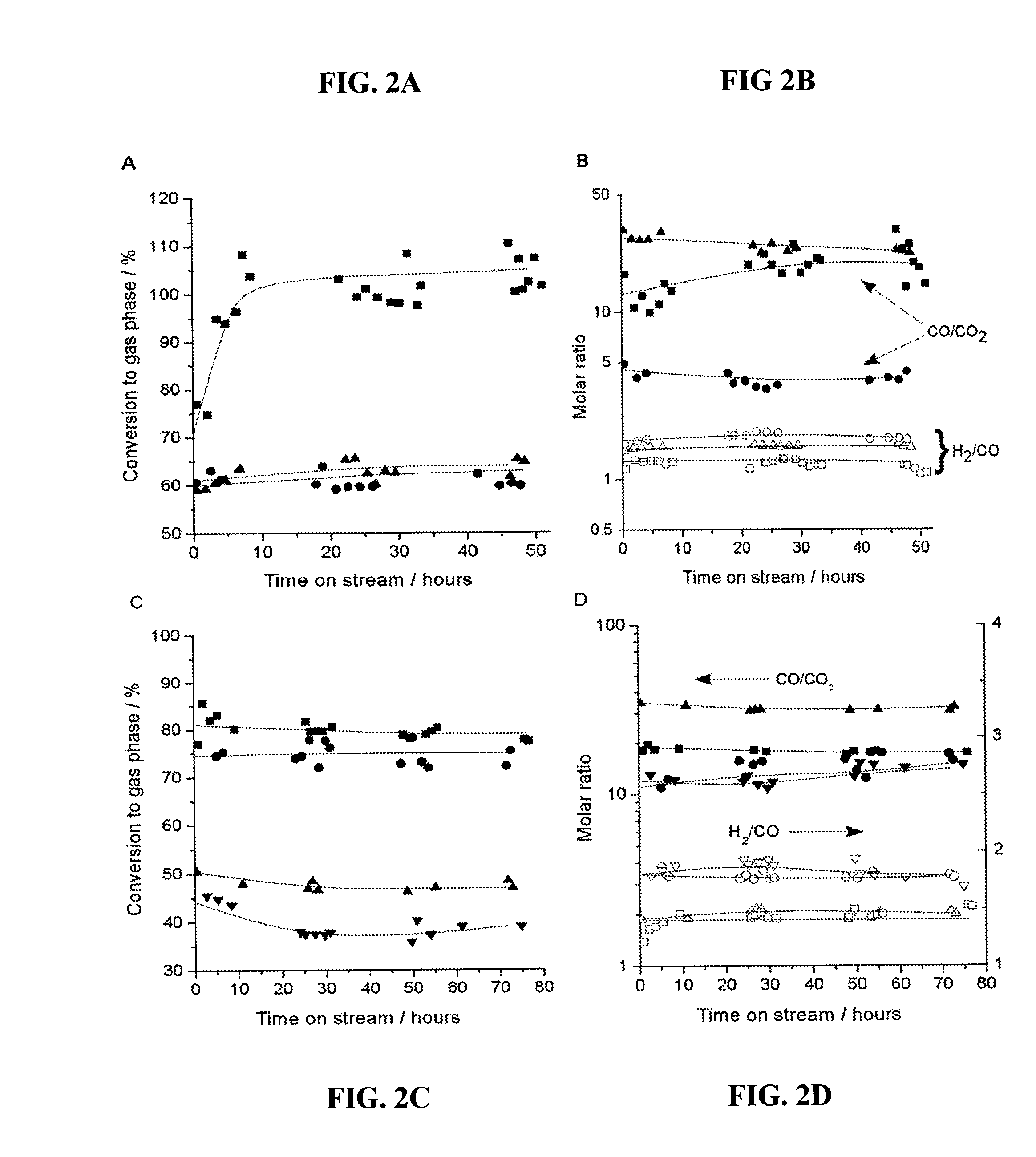
[0104]A catalytic system to produce synthesis gas with varying H2:CO ratios was fashioned using two catalyst beds, the first of which was a Pt / C bed to achieve 100% conversion of glycerol to produce a H2 / CO gas mixture, followed by a second catalyst that was effective for water-gas shift, such as 1.0% Pt / CeO2 / ZrO2 containing redox sites to promote water-gas shift (31, 32). As shown in FIGS. 4A and 4B, this two-bed catalyst system achieved 100% conversion of glycerol, and the H2:CO and CO:CO2 ratios remained stable for at least 48 hours time-on-stream. The values of 1.33 and 14 for the H2:CO and CO:CO2 ratios, respectively, for the Pt / C catalyst indicate a negligible contribution from the water-gas shift reaction; however, the significant increase in the H2:CO ratio and the corresponding decrease in the CO:CO2 ratio for the two-bed catalyst system indicate that the Pt / CeO2 / ZrO2 catalyst has achieved effective water-gas shift co...
PUM
| Property | Measurement | Unit |
|---|---|---|
| temperature | aaaaa | aaaaa |
| temperature | aaaaa | aaaaa |
| temperature | aaaaa | aaaaa |
Abstract
Description
Claims
Application Information
 - R&D
- Intellectual Property
- Life Sciences
- Materials
- Tech Scout
- Unparalleled Data Quality
- Higher Quality Content
- 60% Fewer Hallucinations
Browse by: Latest US Patents, China's latest patents, Technical Efficacy Thesaurus, Application Domain, Technology Topic, Popular Technical Reports.
© 2025 PatSnap. All rights reserved.Legal|Privacy policy|Modern Slavery Act Transparency Statement|Sitemap|About US| Contact US: help@patsnap.com


