Electric fence energiser
a technology of energiser and electric fence, which is applied in the direction of self-interrupter, ac network voltage adjustment, electric variable regulation, etc., can solve the problems of insufficient peak pulse voltage of 1200v, insufficient energiser type, and limited power level of energiser type,
- Summary
- Abstract
- Description
- Claims
- Application Information
AI Technical Summary
Benefits of technology
Problems solved by technology
Method used
Image
Examples
second embodiment
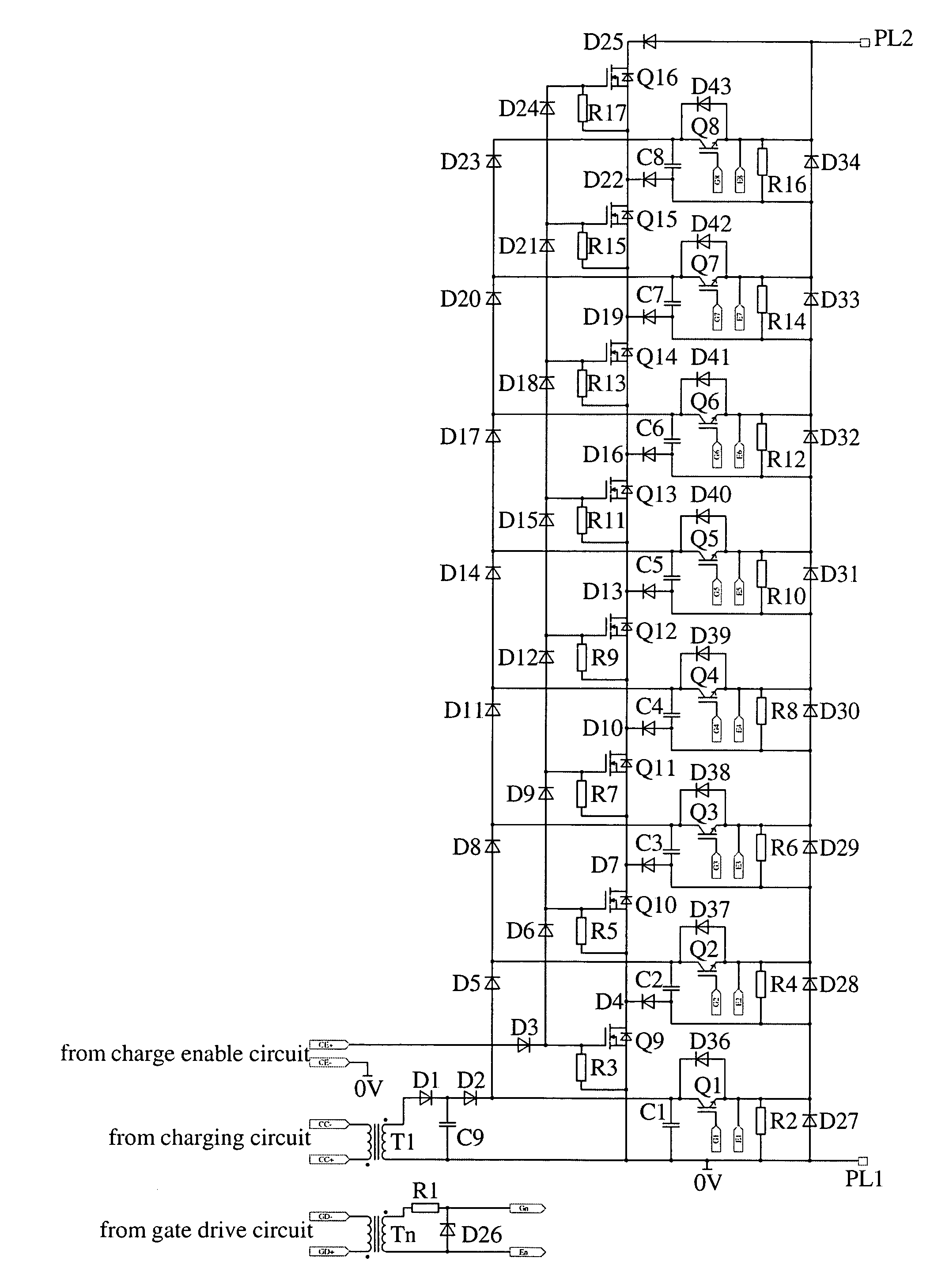
[0045]FIG. 4 is a circuit diagram of an electric fence energiser incorporating the present invention
[0046]FIG. 5 is a circuit diagram as shown in FIG. 4 but illustrating the charging state of the energiser,
[0047]FIG. 6 is similar to FIG. 5 but showing the energiser in a discharge state, and
[0048]FIG. 7 is a graphical representation of a possible pulse voltage waveform.
DESCRIPTION OF PREFERRED EMBODIMENTS OF THE INVENTION
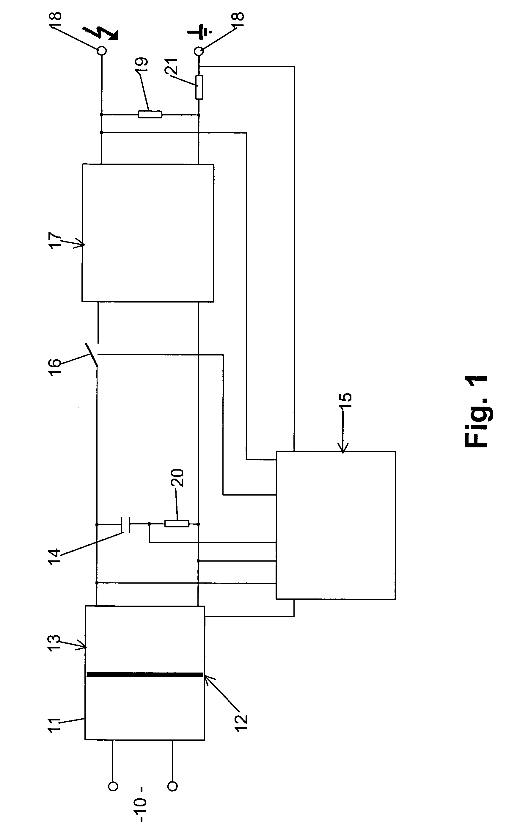
[0049]Referring to FIG. 1 there is shown an electric fence energiser which is powered from an energy source 10, which may be AC mains supply, a battery, solar panel or other source. The power source is connected to power supply circuit 11 which may incorporate an electrical isolation barrier 12. The power supply circuit 11 is coupled to charging circuit 13 which, as shown, has its output connected to a high voltage energy storage capacitor 14. The capacitor 14 is able to be charged up to the required (or desired) output voltage. As previously described, energy storag...
first embodiment
[0128]As the charging circuit only has to generate 1000V the design is easier, lower cost and simplified over the This is especially the case with the switching transformer (if employed) which becomes simpler, lower cost and may offer improved reliability. Also other methods of charging the energy storage capacitors can be used e.g. by means of a mains “voltage doubler” circuit.
[0129]With the second embodiment the charging voltage can more easily be generated from a low supply voltage such as 12V or 24V. Thus the voltage can be generated by using battery supply, battery backup and operation from solar panels as well as from mains supply.
[0130]With the second embodiment, each switching transistor can be controlled independently thus it is possible to independently choose to either discharge or not discharge each energy storage capacitor. For example, in a circuit with eight energy storage capacitors each charged up to a voltage of 1000V it is possible to control the peak output volt...
PUM
 Abstract
Description
Claims
Application Information
 - R&D
- Intellectual Property
- Life Sciences
- Materials
- Tech Scout
- Unparalleled Data Quality
- Higher Quality Content
- 60% Fewer Hallucinations
Browse by: Latest US Patents, China's latest patents, Technical Efficacy Thesaurus, Application Domain, Technology Topic, Popular Technical Reports.
© 2025 PatSnap. All rights reserved.Legal|Privacy policy|Modern Slavery Act Transparency Statement|Sitemap|About US| Contact US: help@patsnap.com


