Reactor for gas phase catalytic oxidation and a process for producing acrylic acid using it

a technology of catalytic oxidation and heat exchanger, which is applied in the direction of metal/metal-oxide/metal-hydroxide catalyst, physical/chemical process catalyst, instrument, etc., can solve the problems of large floor area for their installation, large equipment requirements, and large installation costs of the reactor. achieve the effect of high efficiency

Inactive Publication Date: 2011-03-01
NIPPON SHOKUBAI CO LTD
View PDF22 Cites 13 Cited by
  • Summary
  • Abstract
  • Description
  • Claims
  • Application Information

AI Technical Summary

Benefits of technology

[0018]According to the present invention, a new reaction apparatus for producing acrylic acid from propylene is provided, which, because of the adoption of above-described construction, is free from the problems inherent in conventional fixed bed shell-and-tube reaction apparatus using a single reactor, enables change in composition of the gas in the second stage reaction and allows use of propylene at high concentration.
[0019]The present invention also provides a production method of acrylic acid using the above reaction apparatus, in which accumulation of carbides is rendered difficult even during a long term operation and in consequence the acrylic acid production is conducted at higher efficiency.
[0020]FIG. 1 is a schematic diagram of a conventional reaction appara

Problems solved by technology

When two reactors are used as above-described, however, large costs for installation of the reactors, pipe arrangement and the like are incurred, floor area for their installation must also be large, and large scale equipments are required.
Still in addition, such carbides and the like pollute the catalyst, which induces such phenomena as deterioration in catalytic performance, blocking of the reaction tubes and pressure loss, within a relatively short period.
Hence the composition of the gases for the first stage reaction and the second stage rea

Method used


Image

  • Reactor for gas phase catalytic oxidation and a process for producing acrylic acid using it
  • Reactor for gas phase catalytic oxidation and a process for producing acrylic acid using it
  • Reactor for gas phase catalytic oxidation and a process for producing acrylic acid using it

Examples


example 1

[Preparation of the First Stage Catalyst 1]

[0062]In 300 parts of distilled water, 192.6 parts of ammonium molybdate and 42.2 parts of ammonium paratungstate were dissolved under heating and stirring. Into this solution a liquid mixture of three nitrate solutions obtained respectively by dissolving 79.4 parts of cobalt nitrate in 30 parts of distilled water, 40.4 parts of ferric nitrate in 40 parts of distilled water, and 52.9 parts of bismuth nitrate in 60 parts of nitric acid which had been made of distilled water and 10 volume parts of concentrated nitric acid, was dropped. Successively, 0.234 part of potassium hydroxide as dissolved in 15 parts of distilled water was added. The resultant suspension was heated under stirring and evaporated. The residue was molded and calcined for 8 hours at 460° C. under air flow, to provide a catalyst. The metallic composition of this catalyst was as follows, in terms of atomic ratio:

Mo12Bi1.2Fe1.1Co3K0.05W2.

[Preparation of the Second Stage Catal...

example 2

[Preparation of First Stage Catalyst 2]

[0077]Into 1,000 parts of distilled water, 385.2 parts of ammonium molybdate and 39.3 parts of ammonium paratungstate were dissolved under heating and stirring (solution A). Separately, 264.6 parts of cobalt nitrate was dissolved in 140 parts of distilled water (solution B); 80.8 parts of ferric nitrate, in 80 parts of distilled water (solution C); and 105.8 parts of bismuth nitrate was dissolved in 100 parts of nitric acid which had been made of 100 volume parts of distilled water and 20 volume parts of nitric acid (60%) (solution D). These three kinds of nitrate solutions (solutions B, C and D) were dropped into the solution A. Successively, 0.469 part of potassium hydroxide as dissolved in 30 parts of distilled water was added. Thus obtained suspension was heated, stirred and evaporated, molded into a size of each 8 mm in outer diameter, 3 mm in inner diameter and 7 mm in length, and calcined at 460° C. for 8 hours under an air flow to provi...

example 3

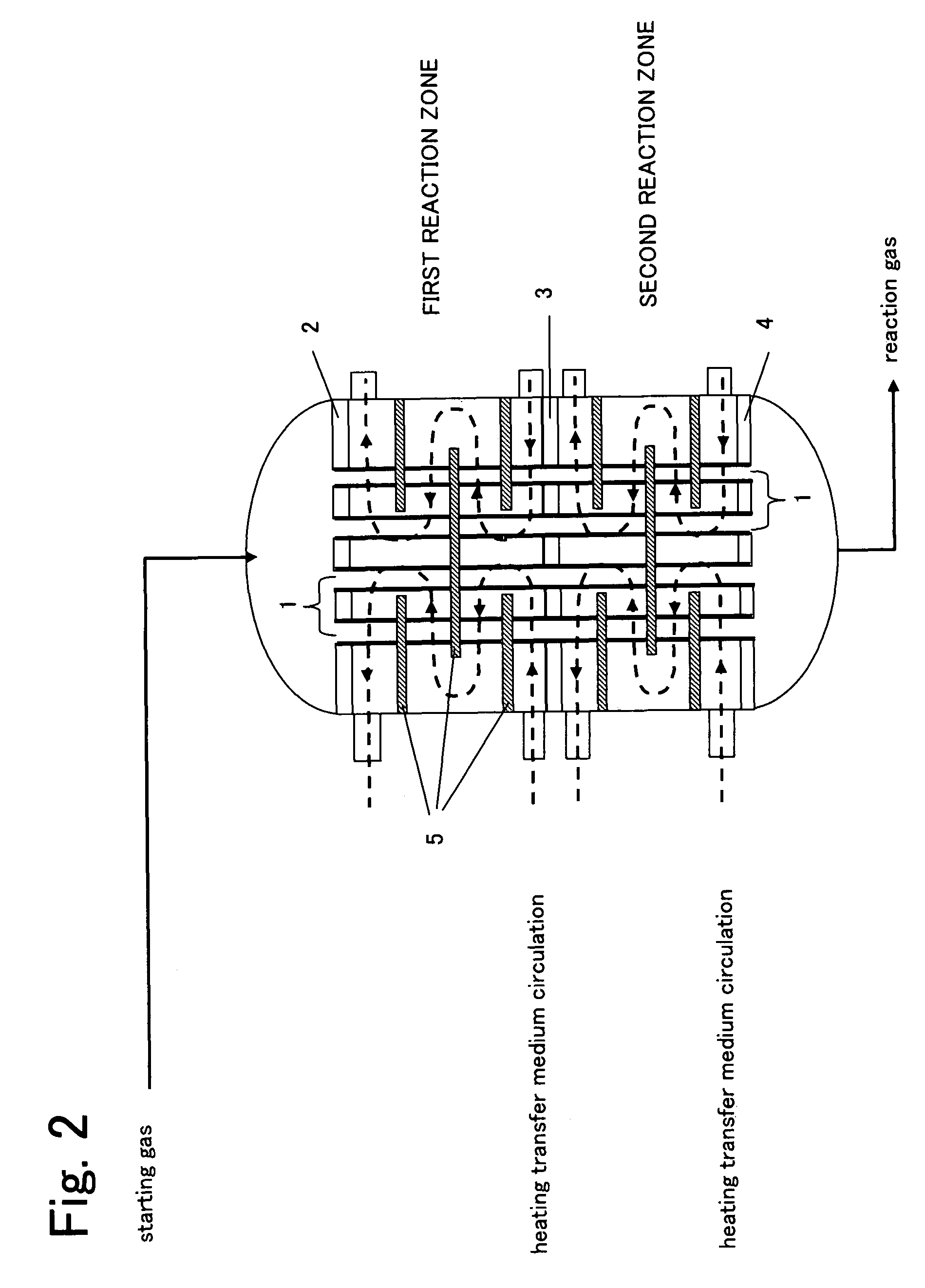
[0092]The reaction was operated under the same conditions as Example 2, except that the additional gas inlet pipe was disposed at a tangential direction to the reactor (cf. FIGS. 3 and 5(c)). The result was as shown in Table 1.

[0093]When condition of the reactor after 4000 hours' operation was examined, deposition of carbides was observed on the catalyst layers over a length of 10 mm from the entrance of the second reaction zone. Thereafter an aeration was carried out under the same conditions as Example 2, and after that removal of the carbides without rapid rise in temperature at the catalyst layer was confirmed. The pressure loss also returned to the level at the incipient period of the reaction. The performance evaluation after that treatment is also shown in Table 1.


PUM

PropertyMeasurementUnit
Temperatureaaaaaaaaaa

Abstract

Conventional gas-phase catalytic oxidation reaction apparatus comprising two reactors for production of acrylic acid is subject to problems of high equipment costs for the reactors and piping, necessity for wide installation area and easy accumulation of carbides generated by autoxidation of acrolein. On the other hand, conventional reaction apparatus comprising a single reactor has the drawbacks that the composition of gas in the first stage reaction and in the second stage reaction cannot be optimized independently of each other, and that the allowable concentration of starting propylene is limited because of the risk of explosion. As a reaction apparatus to solve these problems, this invention provides a fixed bed shell-and-tube reaction apparatus comprising a single reactor, characterized in that the inside of the reactor is divided into two reaction zones of the first reaction zone and the second reaction zone, and that a space equipped with a mechanism for introducing a gaseous substance from outside is provided between the two reaction zones.

Description

TECHNICAL FIELD[0001]This invention relates to a fixed bed shell-and-tube heat-exchanger type reactor for operating gas-phase catalytic oxidation. More specifically, the invention relates to a fixed bed shell-and-tube heat exchanger type reactor which is used for efficiently producing acrylic acid by gas-phase catalytic oxidation of propylene with a single reactor.BACKGROUND ART[0002]Production of acrylic acid by two-stage gas-phase catalytic oxidation of propylene has been widely practiced on industrial scale. This reaction consists of the first stage reaction for gas-phase catalytic oxidation of propylene to acrolein and the second stage reaction for gas-phase catalytic oxidation of the acrolein to acrylic acid.[0003]Heretofore proposed methods for practicing the reaction can be broadly classified into two, i.e., those using two reactors and those using a single reactor.[0004]As one of the methods using two reactors, for example, JP Sho 53(1978)-15314A and JP Sho 55(1980)-102536A ...

Claims


Application Information

Patent Timeline
IPC IPC(8): C07C51/16
CPCB01J8/048B01J8/0492B01J8/0496B01J8/067B01J23/002C07C51/252C07C57/04B01J23/8885B01J37/0221B01J2208/00212B01J2208/00221B01J2208/00513B01J2208/00707B01J2208/025B01J2523/00B01J2523/17B01J2523/55B01J2523/68B01J2523/69B01J2523/13B01J2523/54B01J2523/842B01J2523/845
Inventor TANIMOTO, MICHIONAKAMURA, DAISUKEHAKOZAKI, NOBUYUKI
Owner NIPPON SHOKUBAI CO LTD
Why Eureka
Try Eureka