
External proximal femoral prosthesis for total hip arthroplasty

a femoral prosthesis and hip arthroplasty technology, applied in the field of femoral prosthesis, can solve the problems of bone disease or joint malfunction, undesirable atrophy of the affected area, so as to increase the effort force of the component, extend the ability of the first, and lengthen the effort arm

Inactive Publication Date: 2011-04-26
LI XUE +2
View PDF19 Cites 7 Cited by
  • Summary
  • Abstract
  • Description
  • Claims
  • Application Information

AI Technical Summary

Benefits of technology

[0018]In light of foregoing problems with prior art, particularly, of the existing femoral prosthesis and procedures, it is a goal of the present invention to provide a femoral component for THA, by which patient will no longer require the removal of the entire femoral neck and the prosthesis will not occupy intra-medullar bone of shaft anymore. Beyond that, the rigid stem(s) solidly extended from the lower rim of the component have largely lengthened the effort arm and increased the effort force of the component when it penetrated into inside bone of trochanteric bed. Particularly, it has created a second effort arm in lateral direction. It has largely expanded ability of the first, medial effort arm of the shall. Secondly, the stem has also coupled with the anchoring means for interlocking the component on remnant of proximal femur due to they are titled each other, when installed. Such a function is able to allow the prosthesis is fixed on the bone surface without tightly pressed. Both functions have significantly enhanced ability of the stability of the component on the site regardless the quality of the bone it sits on.
[0019]The object of present invention is to provide an ideal solution, in terms of the medial wall of the cup asymmetrically extended toward inferior medial ridge of the femur provides a longer effort arm length and wide distal opened envelop, which forms a large contact surface and volume of the cavity configured for housing on asymmetrically reamed proximal femur. By same token, more medial section of the wall prolongated toward inferior medial ridge area and more solid base the component sited on.
[0020]Another goal of the present invention is that a peripheral wall with an asymmetrical bell shaped inner contour provides an ideal manner to install femoral prosthesis into human body and eliminate the damage and changes on the anatomic structure of proximal femur, in terms of its biological structure and its blood flow, for example, typically to prevent overcutting bone stock on the medial side of the femoral neck. This would be an ideal solution for younger (20 years old or up) patients, who are more active and require a longer lifetime of the device. Obviously, there are no damages to the intra-medullar canal and bone marrow of proximal femur by such method. The new device would not obstruct any bone growth in both the medullar and shaft of femur of a young patient.
[0021]Still another goal of the present invention is provide fastening method (distal stem coupling with the anchoring means) for the femoral prosthesis, that is no longer a fasten manner by assistance from screw or nail. The interlocking system from the center screw and distal legs firmly anchors the prosthesis on the site with a proper tightness. It has expanded application for many more patients, regardless patient age, quality of bone or disease, which caused the hip defect. Furthermore, the present invention allows a patient to be substantially completely mobile after the operation and a shorter recovery period, because of 1) a simple operative technique, less damage of bone and a shorter period of the operation time and 2) a better interface between prosthesis and remnant femur due multiple mechanical fastenings and biological fastenings applied in the prosthesis. In addition, even if such an implanted femoral prosthesis were to fail at a later stage, it may be easily repaired, removed or replaced by another surgery, which could be a new same type of prosthesis or stem type one. It will expand the entire life span of artificial joint in human body. It will give more hope and promise for young patients.

Problems solved by technology

For instance, if too little stress is applied to the bone, resorption can occur, leading to atrophy of the affected area.
By same token, if too much stress is applied, it may also lead to resorption, or may result in an undesirable atrophy of the affected area.
However, any failure or defect of the factors above leads to bone disease or joint malfunction.
2) The axial loads and torsional moments are transferred to the bone across the bone-prosthesis interface resulting in high shear stresses at the interface.
This disparity in stiffness also contributes to interface shear stresses.
4) There is also poor blood circulation around implanted prosthesis, causing the bone quality to decrease with time.
As a result of these effects, the stem hip prosthesis cannot remain in the body for long period of time.
However, some authors dispute these favorable results pointing out that the bone is not preserved and that both femoral head resorption and acetabular defects lead to subsequent early failure.
1) From material properties point of view, cancellous bone is very different from cortical bone and metal. For example, the elastic modulus of the cortical bone, cancellous bone and stem prosthesis (CoCrMo) are 17.3.times.10.sup.9, 324.6 times.10.sup.6 and 196.times.10.sup.9 (Pa), respectively. In principle, cancellous bone cannot support any load at all. Once cancellous bone comes in contact with the hard surface of metal stem and is loaded with a force beyond its physiological limits, plastic deformation occurs, which accumulates over an extended period of time and manifests itself as migration of the prosthesis.
2) There are changes and differences in the way force is loaded and distributed on the neck of the femur of an intact femur and an implanted stem prosthesis. According to Wolff's law, changes in stress distribution throughout the bone eventually causes definite alteration in its internal structure. For example, the strain applied on femoral head is radially transferred along the length of the stem. This causes a compression force from femoral head to be applied only on inner wall of shaft femur, concentrated on a small and local area of the medullas channel. This leads to local plastic deformation of the cancellous bone.
3) Current surgical procedures of stem THA generally requires the removal of the entire head and neck portion as well as some hard outer cortical bone in order to open the intramedullar canal and install the prosthesis. Such surgery imposes a lot of anatomical changes on the natural system, in terms of blood circulation and nutrient supply to affected area, that it also causes further physical changes in proximal femur with respect to bone quality after the surgery. These problems have been recognized by the orthopaedic community for quite some time. Obviously, these problems are associated with the current design of the hip prosthesis. Aseptic loosening, fatigue fracture, postoperative infection and stress shielding, can directly or indirectly relate to the stem-style design of the prosthesis with respect to weaknesses in both biomechanical and physiological outcomes from the existing THA.
However, the relatively poor survival rate suggests the need for an alternate method for replacing degenerative hips in this group of patients.
These technologies all have their limitations and can not be widely applied.
Due to the large variation of femoral head sizes between patients, it is difficult to develop a device which matches each individual one.
In most cases, the femoral neck has more or less been damaged, so that it can not fully support the load from new head, even though the head has been repaired.
There were a few successful cases in its clinical past, but it has explored defects in its design.
Primarily, it was difficult to shape the retained portion of the femoral neck to match internal shape of the prosthesis, causing the existence of micro movements of the prosthesis around the neck, particularly in early stages of rehabilitation.
This caused too much stress to be applied on the screw and on the bone around the area the screw engaged.
This resulted in either screw breakage or bone resorption.
So it was hard to maintain the prosthesis in a stable condition.
Furthermore, a taller cylinder section of the prosthesis was required to obtain an enough contact surface area of the prosthesis with femoral neck, which reduced the swing range of prosthesis motion.
The angle of its motion was far less than 120 degree. The reduced range of motion (ROM) resulting from this total hip replacement (THR) leads to frequent prosthetic impingement, which may restrict activities of daily living and cause loss or dislocation of acetabular components.
In practice, such a femoral prosthesis has a limited range of patient condition applications and difficulties in clinical use.
But the problem is: the fastener works, like a regular nail or bolt, as a manner as that the nail tightly presses the object on a surface of bone by its small transversal section area of the nail head.
In soft bone area, like lateral tissue of the trochanteric bed, such a friction from nail won't provide much force for holding the prosthesis on site as one expected, because its bone quality is relatively soft.
In these situations, it is undesirable to remove the healthy portion of the femoral neck.
In addition, the stemless femoral prosthesis would eliminate most of problems caused by the stem type prosthesis, but it encounters some problems in its installation and maintaining stability in early stage.
Therefore how to stabilize the stemless prosthesis on site is a key issue for its success.

Method used


Image

  • External proximal femoral prosthesis for total hip arthroplasty
  • External proximal femoral prosthesis for total hip arthroplasty
  • External proximal femoral prosthesis for total hip arthroplasty

Examples


Embodiment Construction

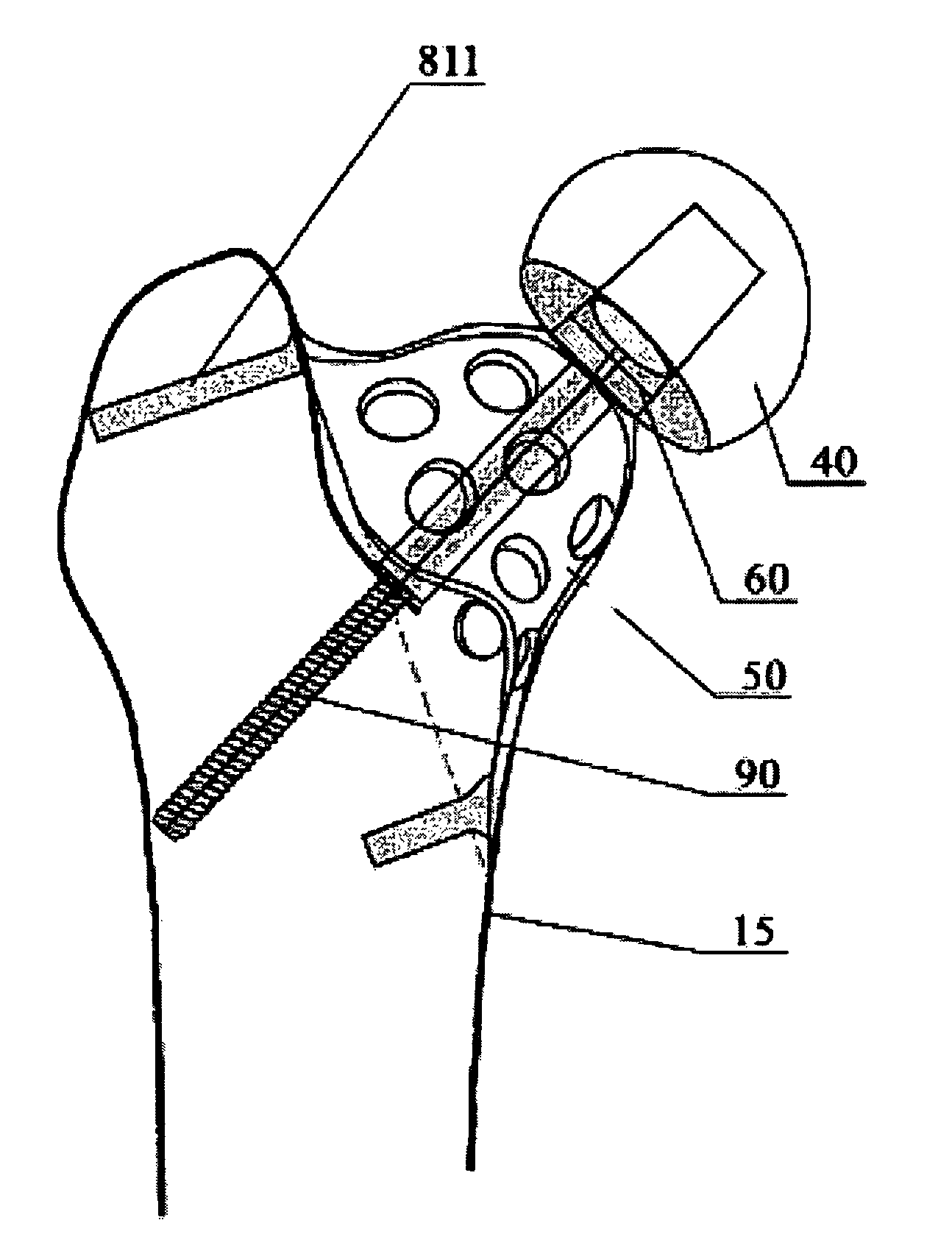
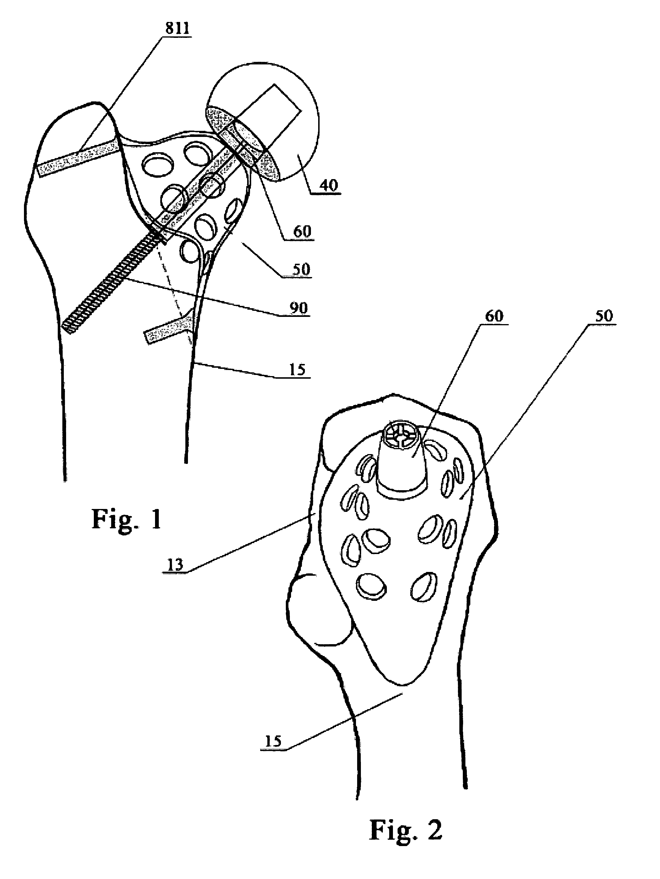
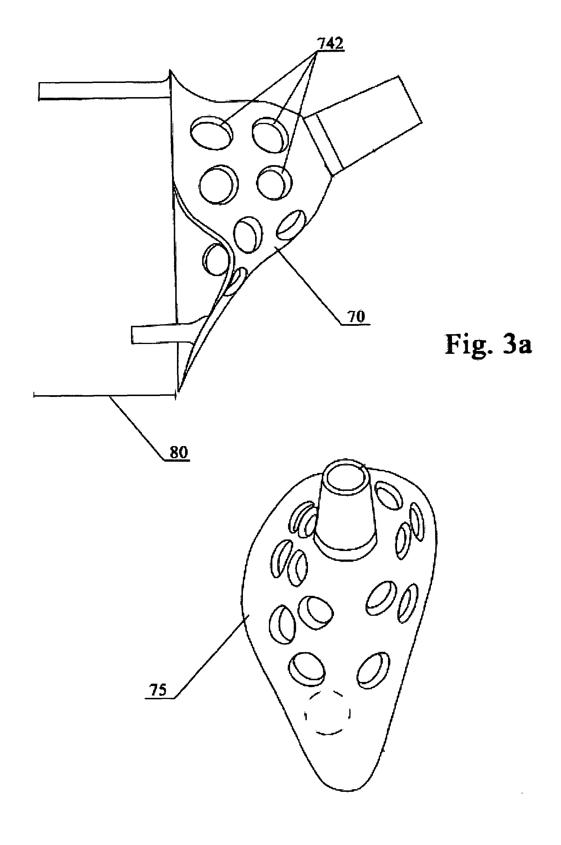
[0027]The present invention is directed to an external proximal femoral prosthesis for THA. Referring to FIGS. 1, and 2, in general, the shell (50) of prosthesis has defined as a hollow bell shape cup with an asymmetric wall configuration, more particularly, extended along direction of inferior medial ridge of the proximal femur for housing into outside retention of either the left or right proximal femur, respectively, by anchoring means for mechanically attaching and securing the shell to the external surface of proximal femur. More particularly, certain aspects of the present invention are directed to a femoral prosthesis that comprises several key features that provide an optimum configuration of the following factors:[0028](1) A minimum removal of bone during implantation, particularly retaining the femoral neck and keep the intramedullar canal of shaft in functioning, which could avoid any side-effect associated with opening intramedullar canal of the shaft.[0029](2) A broad c...


PUM

PropertyMeasurementUnit
angleaaaaaaaaaa
anteversion angleaaaaaaaaaa

Abstract

A external femoral component for mechanically housing onto exterior remnant of natural femur and coupling with articulation elements in order to use in total hip arthroplasty defines as a hollow shell comprised of asymmetrically bell shaped cup, at least one rigid elongated stem downwardly extended from the lower rim of the cup and a plurality of an cylindrical object upwardly protruded from top of the cup for pairing with articulation elements and coupling with anchoring means and the tension anchoring means fixes the hollow shell on the bone surface through an interlocking mechanisms.

Description

FIELD OF THE INVENTION[0001]The present invention relates to a femoral prosthesis to be applied in total hip arthroplasty (THA). More specifically, the prosthesis is an external proximal femoral component and is housed on the outer area of remnant of proximal femur, which includes inferior retention neck, the trochanteric bed and inferior medial ridge of the proximal femoral shaft, and is mechanically fastened by a tension anchoring means during the installation.DESCRIPTION OF THE PRIOR ART[0002]In a natural human femur, most of loading force of the hip is placed on the head first and downwardly distributed through the hard cortex of the femoral neck and further conducted to the femur shaft, eventually to the knee joint. The quality of bone and its peripherals are key factors in the functionality of the hip joint. As well known, proper loading stress and its orientation on the bone can stimulate and facilitate bone growth and regeneration, in terms of its quality (density) and orien...

Claims


Application Information

Patent Timeline
Patent Type & Authority Patents(United States)
IPC IPC(8): A61F2/36
CPCA61B17/86A61F2/3601A61B17/683A61F2310/00976A61B2017/8655A61F2/30767A61F2/30771A61F2002/30224A61F2002/30314A61F2002/30326A61F2002/30332A61F2002/30405A61F2002/30551A61F2002/30579A61F2002/30593A61F2002/30616A61F2002/30774A61F2002/30787A61F2002/30794A61F2002/30841A61F2002/30892A61F2002/30904A61F2002/3611A61F2002/3625A61F2002/3645A61F2002/3647A61F2002/365A61F2220/0025A61F2220/0033A61F2230/0063A61F2230/0069A61F2250/0037A61F2310/00017A61F2310/00023A61F2310/00029A61F2310/00796A61B17/80A61F2002/30309A61F2002/3055A61F2002/3079
Inventor LI, XUEXIE, PINGXIE, KERRY Y
Owner LI XUE
Learn More