Wear resistant hard coating for a workpiece and method for producing the same

a technology of hard coating and workpiece, which is applied in the field of wear resistant hard coating for workpieces and the production of the same, can solve the problems of not significantly improving the tooling performance of materials, and achieve the effect of improving cutting performance and good potential

Active Publication Date: 2011-06-14
OERLIKON SURFACE SOLUTIONS AG PFAFFIKON
View PDF9 Cites 23 Cited by
  • Summary
  • Abstract
  • Description
  • Claims
  • Application Information

AI Technical Summary

Benefits of technology

[0010]Therefore one object of the present invention is to provide an optimized hard coating and a workpiece, especially a cutting tool coated with a hard coating to increase tooling performance with difficult to machine materials such as high speed steels, titanium alloys, nickel alloys, austenitic steels and especially hard materials like hardened tool steel having a hardness of higher 50, preferably of higher 55 HRC. A further object of the invention is to provide such coatings without loosing the excellent oxidation and hot hardness properties of AlCrN. These objects may be achieved by any one of the first two aspects of the invention as described below and in claims 1 and 2. A third object of the invention is to provide an improved cutting tool according to claim 12 used to fabricate parts for mechanical assemblies like e.g. moulds and dies, and other cutting tools like blades as well as a cutting process to perform such operations according to claim 16. One application focus is the improvement of the cutting performance in milling operations with reference to cost reduction, optimization of production sequences and an improved surface roughness of the workpiece as for example.
[0019]However, for the present invention it has been proved advantageously to use a deposition process comprising the step of applying a first lower substrate voltage U1 during deposition of the first coating and applying a second higher substrate voltage U2 during deposition of the second coating. Whereas the first substrate voltage is in the range of 0 V≦U1≦100 V and the second substrate voltage is in the range of 80 V≦U2≦200 V, whereas U2−U1≦20 V. Additionally or alternatively a higher process pressure may be used during deposition of the first coating to reduce intrinsic layer stress and therewith hardness of the first layer. Heating workpieces to temperatures of higher than 550° C., especially to about 600° C. and holding them at this temperature level during the deposition process seemed to give a further beneficial influence to coating adhesion and tool performance.
[0020]A further possibility to influence as mentioned layer properties is to vary the content of certain additional elements or to vary the Al / Cr ratio as mentioned above or with examples below. The hardness of the second nanocrystalline alloyed AlCrN-based layer can be further advanced by adjusting the silicon content to give an optimum in grain refinement resulting in a maximum of hardness. Furthermore, a contributive solution hardening is obtained by as mentioned transition metals, especially of W, Mo, Cb and Ta, which additionally serve as diffusions barrier as e.g. in the grain boundary phase of the hard coating. Altogether, such nanocrystalline alloyed Al / CrN based layers proved to be extremely resistant against high temperatures and oxidation, and therefore being highly effective in protecting the support layer and the substrate from being oxidized. Best performance with cutting operations could be achieved with a texture coefficient QI=I(200) / I(111) in the range of 0.7≦QI≦2 (QI is defined as the ratio of the diffraction intensities I(200) to I(111), assigned respectively to the (200) and (111) plains in the X-ray diffraction spectrum of a material). This corresponds to a balanced growth along (200) and (111) plains. Details regarding the measurement can be seen with FIG. 1.
[0021]Contrary to the second layer the support layer exhibits a columnar growth structure and a higher elasticity through a higher Young's modulus. This proved to be the best combination to transfer mechanical load from the extremely wear and high temperature resistant second layer to the substrate material of the workpiece.
[0022]Alternatively to the two layer set up as described above other layer system can be used to further improve layer performance for special applications. As for example a thin metallic adhesion layer may be used to give an optimized interface between the substrate and the first supporting layer. This adhesion layer may comprise Ti, Cr, TiAl or AlCr and may have a transition zone with growing N, C and / or O content towards the first layer as known to the man of the art.
[0024]Workpiece body or substrate material will be preferably selected at least from one of the followings like high-speed steel, cemented carbide, cubic boron nitride, cermet or a ceramic material. Such coated workpieces can be used for many types of tools, however will be especially useful for cutting tools, as for instance end mills, drills, cutting inserts, or gear cutting tools like hobs. When applied to tools made of cemented carbide, cubic boron nitride, cermet or a ceramic material these coatings have a good potential to improve cutting performance with cutting processes on hard materials—as e.g. hardened steel—having a Rockwell hardness of HRC 50 and higher, or even of HRC 55 and higher as will be demonstrated in detail with examples below.

Problems solved by technology

Such coatings help to improve milling performance for many tooling applications however do not significantly improve tooling performance for materials more difficult to machine such as hardened tool steels, high speed steels, titanium and nickel alloys and austenitic steels.

Method used


Image

  • Wear resistant hard coating for a workpiece and method for producing the same
  • Wear resistant hard coating for a workpiece and method for producing the same
  • Wear resistant hard coating for a workpiece and method for producing the same

Examples


example 1

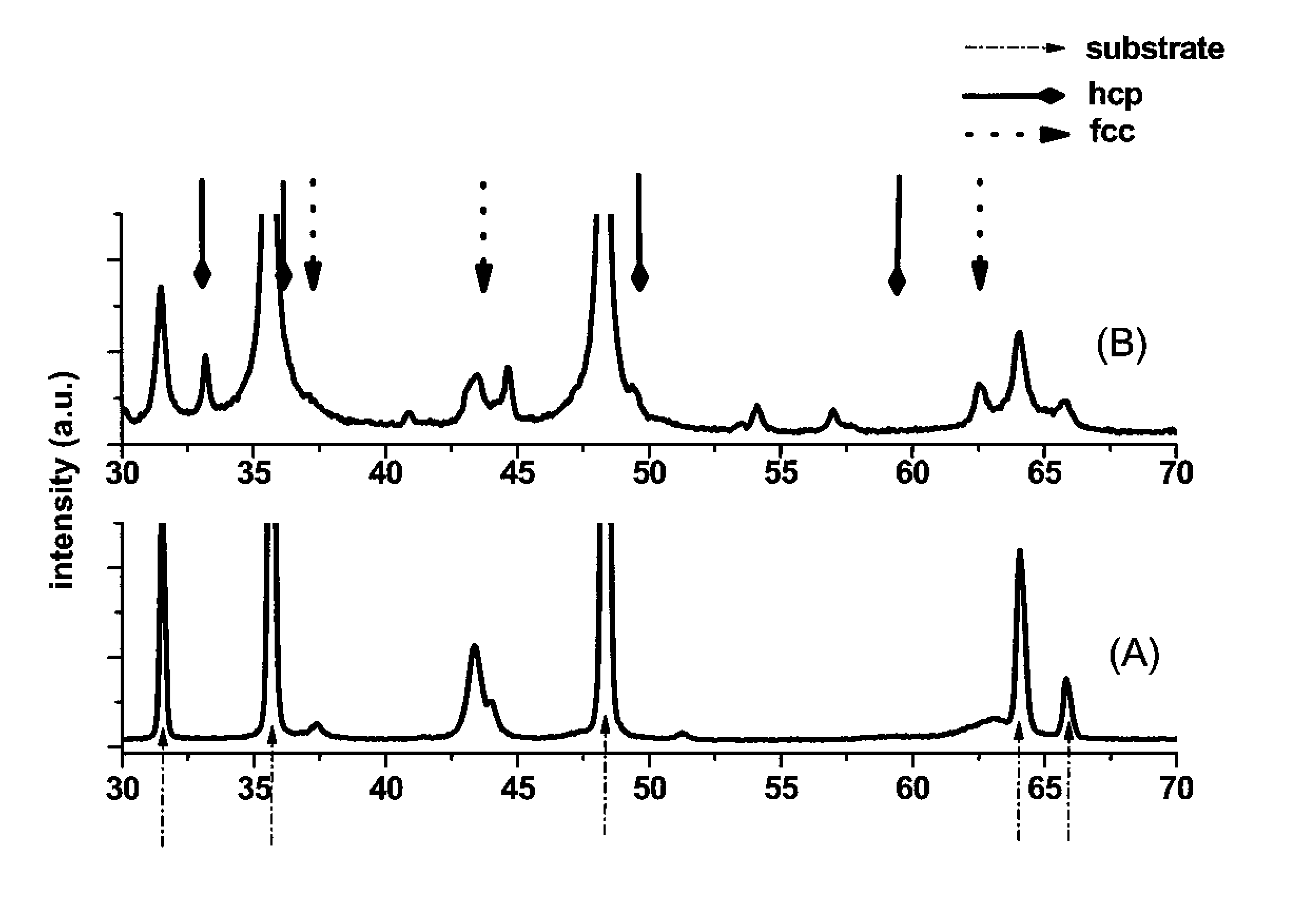
[0045]With example 1 cutting performance of endmills coated with state of the art coatings like TiAlN, AlTiN, AlCrN and (AlCrSiW)N has been compared to a serial of inventive endmills coated with TiAlN or AlCrN / (Al1-c-d-eCrcSidWe)N double layered coatings.

[0046]All coatings have been synthesized by cathodic arc evaporation. Deposition of coatings No 1.4 to No 1.10 has been conducted at a deposition temperature of 600° C. and a total pressure of 3.5 Pa under nitrogen atmosphere. For the first support layer a low bias voltage preferably between −40 V and −100 V has been applied while for the second layer a higher bias voltage of −80 V to −200V has been used, whereas absolute value of bias voltage of the second layer was at least 20 V, preferably 40 V higher than bias voltage of the first layer. Deposition of coatings No 1.1 to No 1.3 has been conducted at a deposition temperature of 500° C. and a total pressure of 3.0 to 4.0 Pa under nitrogen atmosphere.

[0047]Data with reference to com...

example 2

[0050]With example 2 the same deposition parameters were applied as with example 1.

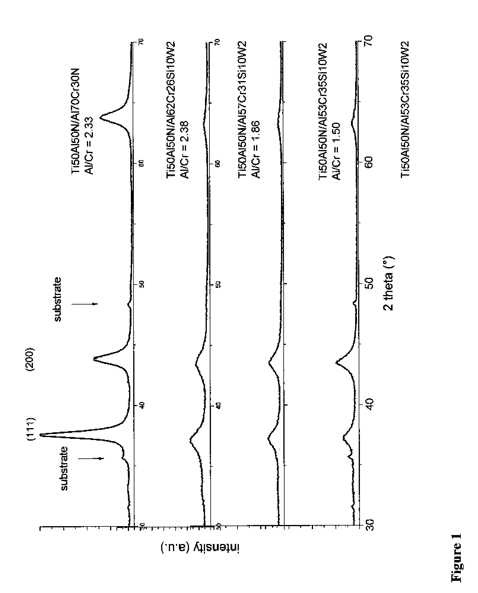
[0051]With experiments 2.1 to 2.3 Si content of the second coating is varied at a constant Al / Cr ratio, with experiments 2.4 to 2.6 ratio of Al / Cr is varied at constant Si content. Only small variations of tungsten—around 2±0.3% to the maximum—were measured for all experiments of example 2, as displayed in table 2.

Milling Conditions:

[0052]

Work piece:DIN 1.2379 (60 HRC)Cutting tool:2-fluted ball nose end-mill, Ø 10 mm, micro graincarbide gradeSpindle rotation:8000 min − 1Cutting speed:200 mmin − 1Feed rate:0.1 mm / toothRadial depth of cut:0.5 mmAxial depth of cut:0.3 mmCoolant:compressed dry airMilling operation:down millingLength of single pass:30 mEnd of lifetime:vbmax > 100 um at the end a single pass

[0053]In table 2, at constant Si content (No. 2.4-2.6) hardness measurements show a decrease of hardness with increasing Al / Cr-content of the second coating. At constant Al / Cr-ratio a maximum of the hard...

example 3

[0055]Milling capacity of innovative coating No 3.4 has been compared to state of the art coatings No 3.1-3.3 during a roughing operation according to the parameters mentioned below. With example 3 the same referring deposition parameters were applied as mentioned with example 1.

Milling Conditions:

[0056]

Work piece:DIN 1.2344 (52 HRC)Cutting tool:2-fluted ball nose end-mill, Ø 10 mm, micro graincarbide gradeSpindle rotation:4690 min−1Cutting speed:80 mmin−1Feed rate:0.15 mm / toothRadial depth of cut:4 mmAxial depth of cut:0.8 mmCoolant:compressed dry airMilling operation:down millingLength of single pass:15.5 mEnd of lifetime:vbmax > 150 um at the end a single pass

[0057]

TABLE 3targetcompositionsupporttarget compostioncuttinglayer s.l.main layerthicknessperformance(% at)m.l. (% at)ratiolifetime atNo.coatingAlCrTiAlCrTiSiWm.l. / s.l.vb = 200 um (m)3.1TiAlN———50—50———933.2AlTiN———66—33———1623.3AlCrN———7030————181.53.4TiAlN / AlCrSiWN50—505731—1021.84264


PUM

PropertyMeasurementUnit
thicknessaaaaaaaaaa
Rockwell hardnessaaaaaaaaaa
temperatureaaaaaaaaaa

Abstract

The present invention provides an optimized hard coating and a workpiece, especially a cutting tool coated with a hard coating to increase tooling performance with difficult to machine materials such as high speed steels, titanium alloys, nickel alloys, austenitic steels and especially hard materials like hardened tool steel having a hardness of higher 50, preferably of higher 55 HRC. This is achieved by a workpiece coated with a wear resistant multilayered comprising at least a first supporting layer and a second nanocrystalline layer, whereas the first layer comprises a coating material of the following composition (TiaAl1-a)N1-x-yCxOy with 0.4<a<0.6, and 0≦x and y<0.3, or (AlbCr1-b)N1-x-yCxOy with 0.5<b<0.7, and 0≦x and y<0.3. The second layer comprises a coating material of the following composition (Al1-c-d-eCrcSidMe)N1-x-yCxOy whereas M stands for at least one element of the transition metals of group 4, 5, 6 of the periodic system except Chromium and 0.2<c≦0.35, 0<d≦0.20, 0<e≦0.04.

Description

CROSS-REFERENCE TO RELATED APPLICATION[0001]This is a C-I-P of application Ser. No. 11 / 690,270 filed Mar. 23, 2007 and incorporated here by reference.BACKGROUND OF THE INVENTION[0002]The present invention relates to a hard and wear-resistant coating designed for tooling of materials difficult to machine such as e.g. hardened tool steels, stainless steels and titanium alloys. Such an application of extreme machining conditions requires a coating having an excellent wear-resistance, hot-hardness and oxidation resistance combined with a high toughness and a good adhesion.[0003]The present invention further relates to the fabrication process of such a wear resistant coating, i.e. a defined PVD arc evaporation process.[0004]It further relates to a coated workpiece, especially a tool having a body made from a cemented carbide, a cermet, a cubic boron nitride (CBN) or high speed steel.DISCUSSION OF RELATED ART[0005]AlTiN is a widely used PVD coating for machining of hardened steel. However...

Claims


Application Information

Patent Timeline
Patent Type & Authority Patents(United States)
IPC IPC(8): B32B9/00
CPCC23C4/128C23C14/0641C23C14/0664C23C30/005C23C28/042C23C28/044C23C28/42Y10T428/24983Y10T428/31678Y10T83/04Y10T407/27Y10T428/265Y10T428/24975B82Y40/00C23C28/048C23C28/40C23C4/137C23C14/06C23C14/08C23C14/16
Inventor LECHTHALER, MARKUSREITER, ANDREAS
Owner OERLIKON SURFACE SOLUTIONS AG PFAFFIKON
Why Eureka
Try Eureka