
Induction melting apparatus employing halide type crucible, process for producing the crucible, method of induction melting, and process for producing ingot of ultrahigh-purity Fe-, Ni-, or Co-based alloy material

a technology of induction melting and crucible, which is applied in the direction of electrical equipment, lighting and heating equipment, furnace linings, etc., to achieve the effect of promoting secondary refining, safe maintenance of high refining performance, and wide application range of induction-melting

Inactive Publication Date: 2011-06-28
KOBE STEEL LTD
View PDF14 Cites 8 Cited by
  • Summary
  • Abstract
  • Description
  • Claims
  • Application Information

AI Technical Summary

Benefits of technology

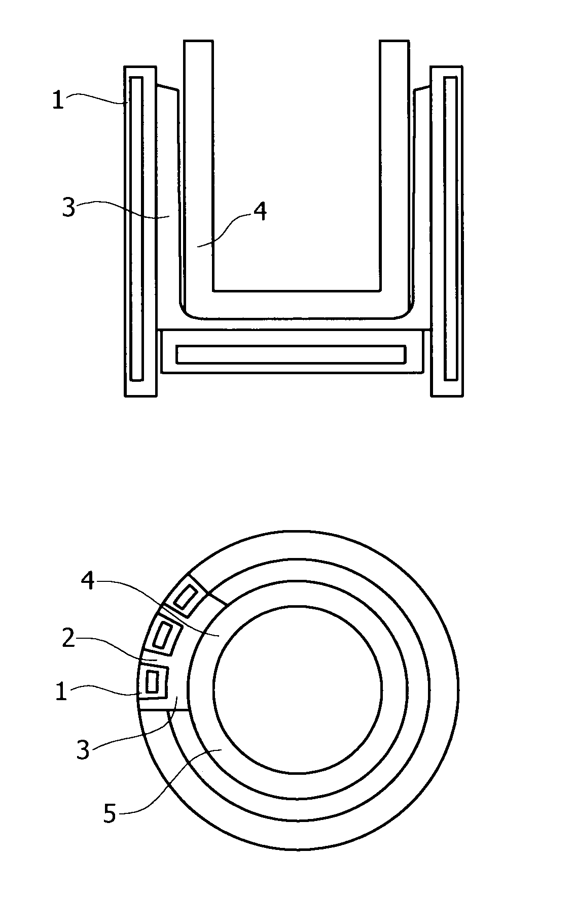
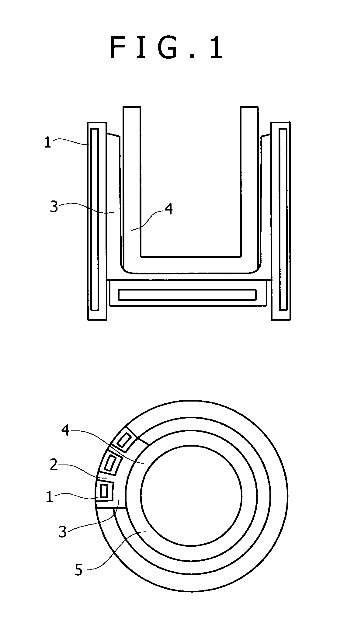
[0036]As described in the foregoing, with the present invention, the crucible having a forcible cooling function by the action of the tubular segments is incorporated in the induction-melting apparatus, and a halide, that is, a solid halide layer is provided between the respective tubular segments adjacent to each other. Furthermore, since the same solid halide layer is formed on the inner peripheral surface of the peripheral body part of the crucible as well, high refining performance can be safely maintained even if use is made of the halide-base flux as a refining agent, and induction-melting of ultrahigh-purity alloys can be concurrently effected without causing deterioration in power efficiency. In addition, not only a sufficient amount of the halide-base refining flux can be used to thereby raise a refining degree but also an application range of the induction-melting can be further expanded. Further, even in the event that the halide layer of the peripheral body part is partially broken by a molten alloy bath at a high temperature, allowing otherwise infiltration of the molten metal, it is possible to cause the molten metal to undergo cooling and solidification by virtue of the forcible cooling function of the crucible, thereby preemptively preventing the induction coil disposed on the outer side from being damaged.
[0037]As described in the foregoing, the present invention also provides the method for melting the ultrahigh-purity alloying materials, having a basic feature in that the primary melting by use of the cold-crucible type vacuum induction melting method, executed in combination with the use of the halide-base flux, is combined with the secondary melting by use of the electron-beam melting method. In the primary melting, the molten metal is held in contact with the halide-base refining flux in the water-cooled crucible for not less than 5 minutes. The method for melting the ultrahigh-purity alloying materials has an important feature in that a primary refining reaction sufficiently proceeds by so doing, and in the secondary melting, the primary ingot is melted in a atmosphere at a low pressure not higher than 0.5 Pa, thereby promoting secondary refining due to evaporation of impurity metals. With this method, it has become possible to produce high-purity Fe-base, Ni-base, and Co-base alloys, each containing less than 8 wt % of Cr and Mn, large in ingot size, that is, each having a reduced impurity level of (C+O+N+S+P)<100 ppm, (C+O+N+S+P)<50 ppm, and Ca<10 ppm, which used to be industrially difficult to produce by the conventional method, so that metal materials excellent in corrosion resistance can be provided.

Problems solved by technology

Further, upon melting for refining an alloying material of high-purity, and high cleanliness, if a large amount of a halide-base refining flux is used for the purpose of desulfurization, and dephosphorization in a molten metal, there arises a risk that the flux in a molten state at a high temperature will cause the melt-damage of refractories making up a crucible, such as silica, alumna, magnesia, or calcium oxide, and so forth.
In each of the following Patent Documents 1 to 3, there is disclosed an excellent method for refining stainless steel through desulfurization, and dephosphorization, using such a system as described in the foregoing, however, even with this method, another problem caused by the water-cooled copper crucible is encountered.
More specifically, if an operation is carried out in the copper crucible cooled down to on the order of 200° C., in a state of a molten metal and a refining flux being in direct contact therewith, a temperature of the refining flux becomes excessively low, thereby impairing refining effects.
Or an amount of heat transfer from a molten pool to the copper crucible becomes excessively large, leading to deterioration in power efficiency.
However, a finely controlled operation cannot necessarily be executed with ease owing to latent problems such as constraints from the viewpoint of a water-cooling structure of the copper crucible, constraints from the viewpoint of safety of the copper crucible, and so forth.
After all, with a method whereby the cold-crucible melting method is combined with flux refining, problems remain in that there occur not only deterioration in the refining effect itself, attributable to a drop in temperature of the refining flux due to a cooling action, but also deterioration in the power efficiency, due to a large amount of heat transfer from the molten metal.
Further, with the heat-resistant crucible provided with the cooling pipes, disclosed in Patent Document 4, a halide-base flux will react with the refractories of the crucible, so that it is difficult to make use of refining using flux.
A method for applying mold wash of refractory ceramics to the crucible, as disclosed in Patent Document 5, is not suitable for use when applying mold wash with a refining flux having high refining performance at a low melting point.
As requirement quality is more diversified, or becomes higher in grade, it is a major problem emerging upon melting of an ultrahigh-purity alloying material such as a Fe-base, an Ni-base, or a Co-base alloying material that impurity elements such as oxygen (O), nitrogen (N), sulfur (S), phosphorus (P), and so forth need be comprehensively reduced to the utmost limit.
However, since in most cases, use is made of a melting vessel made of refractories based on oxides such as magnesia, alumina, and so forth, there is a risk in principle that oxygen is supplied from those refractories to a molten metal, so that there are limitations to oxygen removal.
However, because halide-base refining agents will cause a crucible made of the oxide-base refractories to undergo intense melt-damage, use of this kind of refining flux is almost impossible in reality.
The reason for that is because the refining flux such as Ca—CaF2, and so forth is harmless to the water-cooled copper crucible although the same will cause considerable damage on the crucible made of oxide-base refractories at a melting temperature.
Further, it is also known that if Ca out of Ca—CaF2, and so forth, for use in the refining flux for production of stainless steel, is mixed in the stainless steel, this will cause Ca ranging from several tens of ppm to several hundred ppm to remain in the stainless steel, thereby considerably deteriorating corrosion resistance thereof.
In the following Patent Document 1, there is disclosed a method whereby an alloying material is first dephosphorized with a Ca—CaF2 base flux, to be treated again with a CaF2 flux, thereby reducing Ca content of an alloy to not more than 30 ppm, however, with this two-stage method, reaction efficiency is not so good as expected.
Those methods certainly seem to be good methods in terms of dephosphorization, or decalcification, however, those methods are not considered satisfactory from the viewpoint of an object for comprehensively reduce, and remove a series of impurities, including C, O, N, S, P, and Ca, to the limits, as expected by the invention.
Further, besides the cold-crucible induction melting method described as above, the electron-beam melting method, and a vacuum melting method whereby the vacuum arc melting method using the water-cooled copper crucible is adopted have been in widespread use, however, any of those methods are intended for removal of specific elements, and non-metal inclusions, having not reached as yet a mature state for comprehensively reducing impurities such as C, O, N, S, P, Ca, and so forth.Patent Document 1: JP-A No. 2003-55744Patent Document 2: JP-A No. 2002-69589Patent Document 3: JP-A No. 2000-248310Patent Document 4: JP-A No. 2003-227687Patent Document 5: JP-A No. 5 (1993)-322451Patent Document 6: JP-A No. 11 (1999)-246919Patent Document 7: JP-A No. 11 (1999)-246910

Method used


Image

  • Induction melting apparatus employing halide type crucible, process for producing the crucible, method of induction melting, and process for producing ingot of ultrahigh-purity Fe-, Ni-, or Co-based alloy material
  • Induction melting apparatus employing halide type crucible, process for producing the crucible, method of induction melting, and process for producing ingot of ultrahigh-purity Fe-, Ni-, or Co-based alloy material

Examples


working example

[0079]In the case of this working example, the primary melting was executed with the use of a cold-crucible induction-melting apparatus of the following facility specification, provided with a vacuum chamber, thereby melting 50 kg of stainless steel (SUS316L) for refining. With respect to each of comparative examples, there was conducted a melting test on the same variety of stainless steel as a target.[0080]Max. Output: 400 kW[0081]Power supply frequency: 3 kHz[0082]Water-cooled copper crucible: inside dia.; φ210 mm, the number of segments; 24 pieces (slit interval; 0.5 mm)[0083]Melting capacity: stainless steel 40 to 50 kg / heat

(Primary Melting)

[0084]First, electrolytic iron was charged into the water-cooled copper crucible of the cold-crucible induction-melting apparatus to be subjected to induction melting in a vacuum. In this process step, there was observed a state of molten metal frothing up as a result of oxygen in the electrolytic iron coming to react with charged carbon, an...


PUM

PropertyMeasurementUnit
pressureaaaaaaaaaa
temperatureaaaaaaaaaa
melting pointaaaaaaaaaa

Abstract

There is described a method for producing ultrahigh-purity Fe-base, Ni-base, and Co-base alloying materials to achieve impurity levels of (C+O+N+S+P)<100 ppm, and Ca<10 ppm, in the form of a large ingot, using a refining flux while forcibly cooling the crucible. A refining flux selected from the group consisting of metal elements of the Groups IA, IIA, and IIIA of the Periodic Table, oxides thereof, halides thereof, and mixtures thereof, is added to the molten metal during primary melting and the molten metal is held in contact with the refining flux for at least 5 minutes before tapping. Thereafter, the molten metal is caused to undergo solidification inside a mold, thereby producing a primary ingot. Subsequently, secondary melting is executed by an electron-beam melting method whereby while the primary ingot is sequentially melted in a water-cooled copper mold at a low pressure, the molten metal as-solidified state is pulled out from an outlet side of the water-cooled copper mold, thereby forming an ingot product.

Description

TECHNICAL FIELD[0001]The invention relates to an induction-melting apparatus for use in refining a high-grade stainless steel, superalloy, and so forth, of which high-purity, and high cleanliness are required, by melting, and a method for induction-melting of alloying materials, using the induction-melting apparatus.BACKGROUND ART[0002]For a common induction-melting apparatus, use is made of a relatively small-sized apparatus of a type using a crucible formed of refractories made of sintered magnesia or alumina, provided inside an induction coil, or a large-sized apparatus comprising a crucible layer formed by sintering the surface layer of powdery refractories. With any type of those apparatuses, it is a common practice to use the same after filling refractory powders in-between the induction coil, and the crucible layer as sintered in order to protect the crucible from high temperature.[0003]For induction-melting of material having a high melting point, such as iron-base alloy, ni...

Claims


Application Information

Patent Timeline
Patent Type & Authority Patents(United States)
IPC IPC(8): B22D27/02C22B9/16C22B9/10
CPCC04B35/5152C04B35/553C04B35/66C21C5/5241C22B9/003F27B14/061F27B14/10F27D1/0006H05B6/22C22B23/06Y10T29/49Y02P10/25
Inventor KUNII, KAZUTAKAKUSAMICHI, TATSUHIKONAKAYAMA, JUMPEIKIUCHI, KIYOSHI
Owner KOBE STEEL LTD
Learn More