Method and apparatus for an environmentally hardened ethernet network system

a network system and environment-friendly technology, applied in the direction of cable laying apparatus, data switching network, waveguide, etc., can solve the problems of limiting the design transmission distance, the cost of fiber cable termination and outdoor installation is much higher, and the fiber cable has much higher capital and outdoor installation costs to protect the delicate fibers, so as to avoid the limitation of the distance between the csma/cd protocol and the extension of the rang

Active Publication Date: 2011-10-25
RATEZE REMOTE MGMT LLC
View PDF158 Cites 10 Cited by
  • Summary
  • Abstract
  • Description
  • Claims
  • Application Information

AI Technical Summary

Benefits of technology

[0013]For reliability in the outdoor environment, the NAN requires the use of a mechanically and electrically reliable connector. An example of a preferred embodiment is a DB-9 plug and jack for the cable and the network equipment. The preferred connectors are configured to maintain adequate physical and electrical contact over a range of operationally harsh environmental conditions. The connectors preferably have gold plated pins and sockets and make contact with each other over the entire circumference and length of the pins; the plugs and receptacles of the special connectors interlock with protective housings or shells that shield the contact area from dirt, moisture and EMI and that contain within the contact area protective contact dielectric gel; and the plugs and receptacles have secured mechanical clasping mechanisms such as screws and threads that clamp the connectors together, providing strain relief from cable torque or stress. The entire construction provides much more mechanical robustness and environmental integrity for either indoor or outdoor network data connections.
[0014]According to a specific embodiment of the invention, high performance physical layer transceivers (herein high PHYs) are employed at lower than specified clock rates in the network equipment to extend range and increase reliability. According to a further specific embodiment of the invention, full duplex switched packet transmission techniques are used between switched nodes thereby avoiding distance limiting CSMA / CD protocols.
[0015]To increase the data rate of the NAN backbone with minimal cost, several copper (or fiber) ports can be “trunked” over a single CAT-5 by using all 4 pairs, 2 for each of the 2 ports. In trunking, UTP pairs support simultaneous transmission in a common direction in a manner that share data traffic between them. This technique can provide a data rate increase from 100 Mbps to 200 Mbps full duplex (400 Mbps total) with very little increase in cost. The DB-9 connector can be structured to provide both ports at a single connector to facilitate the trunking option, or the power lines can be branched within a secure enclosure to a high current power connector and power distribution network, from which power is shunted to local equipment.

Problems solved by technology

However, the designated transmission distances are limited to the IEEE 802.3 specified 100 meter maximum that is based upon CSMA / CD collision domain and CAT-5 attenuation criteria.
Hence, when significantly longer distances are required (and economics justify it), the more expensive 100Base-FX fiber optic technique has been employed.
Compared to CAT-5, fiber cable has much higher capital and outdoor installation costs to terminate and to protect the delicate fibers.
Fiber transceiver nodes are also much more expensive than for copper based twisted pair.
Fiber cable is a dielectric and cannot conduct electrical power.
However, RJ-45 connectors have reliability limitations related to the mechanical design of the contacts.
Outdoor deployment of RJ-45 connections has resulted in reliability concerns.
The contact is a low reliability single-surface contact because the contact area is so small and because the RJ-45 plug is held in the jack by a plastic arm that is not positive enough to hold the plug securely in the jack when torque or stress is applied to the CAT-5 wire mechanically crimped to the jack.
Consequently, particularly in harsh outdoor installations and even in indoor environments, the RJ-45 jack demonstrates reliability problems.
The mechanical problems are increased in the outdoor environment not only due to the temperature extremes, high humidity and dirt levels but also because the outdoor gel filled CAT-5 that is deployed in outdoor environments is so stiff that it multiplies the torque applied to the plug and increases the unreliability of the single-surface connections.
But when the installation of certain components must be made in locations that are not conveniently proximate to AC power sources, power must be supplied either by installing retrofit AC power circuits, by using batteries or by employing the CAT-5 wiring itself.
For example, a 6 Watt switch operating at 3.3 V consumes nearly 2 A, which in turn dictates that a 100 meter length of CAT-5 would drop nearly 34 V and 60 Watts in the wire alone (clearly impractical).
However, the technique described in this patent remains impractical (for longer distances, at least).
The U.S. Pat. No. 5,994,998 technique is further limited by the following factors: 1) the degradation of the signal to noise ratios caused by increased noise generated by power supply current through greater lengths of cable on top the decreased signal level; and 2) the high cost of quality inductors required to isolate signals from power without seriously altering the delicate IEEE 802.3u spec for 100Base-TX signals.
Further, if the other 2 pairs are used for a second set of signals to a separate network device, then crosstalk noise becomes a serious issue over longer lengths of CAT-5 approaching the 100 m limit.

Method used


Image

  • Method and apparatus for an environmentally hardened ethernet network system
  • Method and apparatus for an environmentally hardened ethernet network system
  • Method and apparatus for an environmentally hardened ethernet network system

Examples


Embodiment Construction

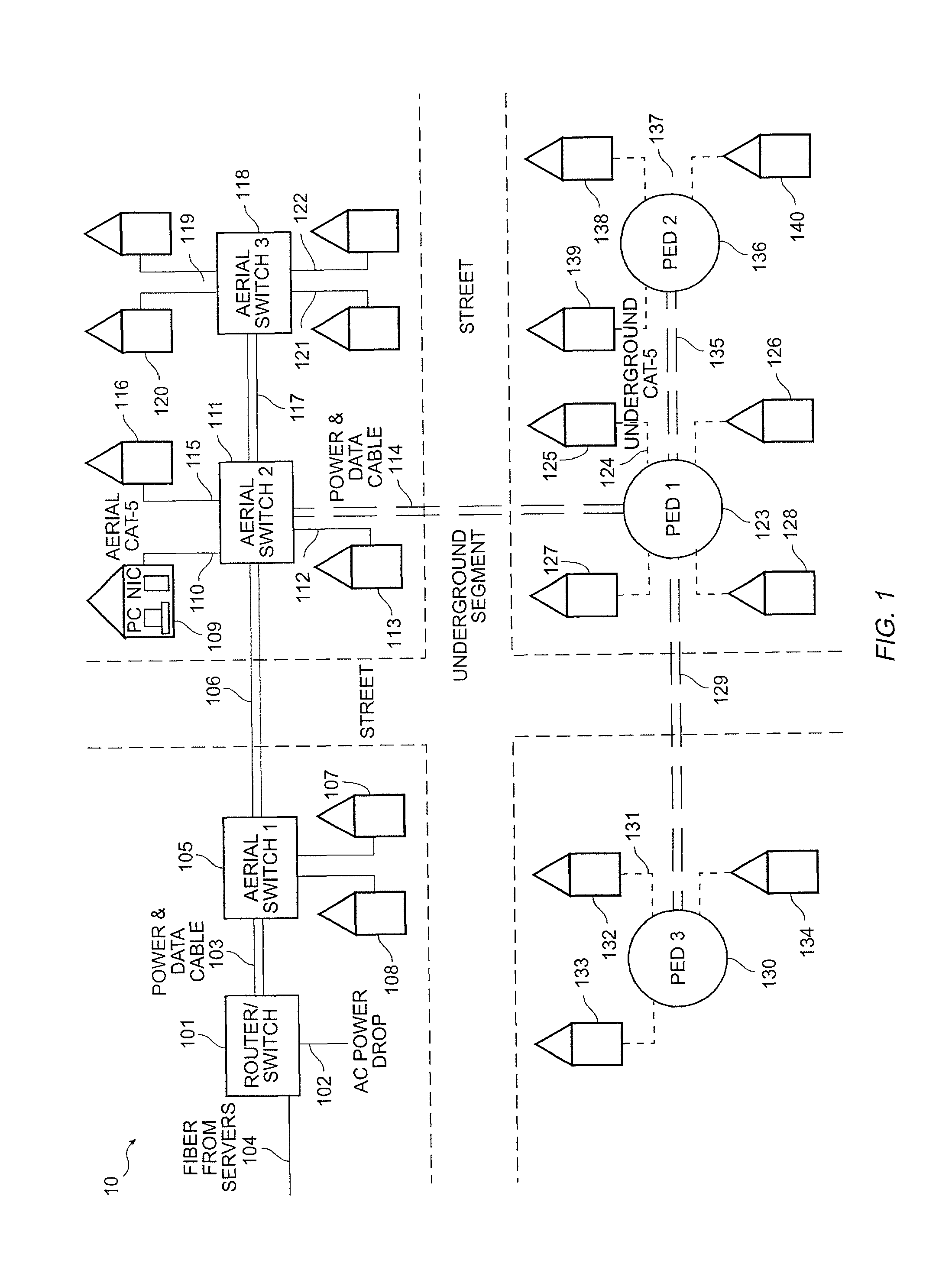
[0022]FIG. 1 is a diagram of an environmentally hardened network, herein a NAN system 100, that integrates both data and power distribution function. A NAN Distribution box 101 contains a switch or, if enhanced, a router for connecting to a larger environmentally hardened ETHERNET network. It is assumed that there is a network operation center (NOC) (not shown) providing various network services via ETHERNET protocols. This distribution may be via fiber cabling 104, for example, The NAN fiber uplink cable 104 could also be part of a routed fiber loop running gigabit Ethernet or other high-speed fiber protocols. Distribution box 101 may be powered by AC power drop 102 that sources metered AC power (115 / 230V AC in the US) from a utility company service line or generator. Distribution box 101 supplies power and data through a cable 103 according to the invention to at least one distribution segment of the NAN, as illustrated. NAN cable 103 carries data and power to the uplink port of a...


PUM


Abstract

In an environmentally hardened network, a data and power distribution cable is employed in connection with reliable end connectors, high performance physical layer transceivers clocked at a lower rate than is specified and full duplex switched packet transmission techniques between switched nodes in order to extend operational distance between network elements. In a specific embodiment, the data and power distribution cable comprises a data distribution element, a power distribution element, an optional strain distribution element, an optional hollow conduit, and an extra shield and outdoor sheath. The cable may incorporate: 1) a Gel filled outdoor UTP (CAT-5) cable; 2) end connectors of type DB-9 [D-Sub] for connection of the UTP to network equipment; 3) power transmission cable of wire gauge sufficient to carry the power required by network equipment (switches, etc) for the specific segment of the network; and optionally 4) a hollow conduit that permits installation of optical fiber before or after installation of the cable.

Description

CROSS-REFERENCES TO RELATED APPLICATIONS[0001]NOT APPLICABLESTATEMENT AS TO RIGHTS TO INVENTIONS MADE UNDER FEDERALLY SPONSORED RESEARCH OR DEVELOPMENT[0002]NOT APPLICABLEREFERENCE TO A “SEQUENCE LISTING,” A TABLE, OR A COMPUTER PROGRAM LISTING APPENDIX SUBMITTED ON A COMPACT DISK[0003]NOT APPLICABLEBACKGROUND OF THE INVENTION[0004]The present invention relates to an environmentally hardened ETHERNET-type network, herein called a Neighborhood Area Network (NAN). More particularly the invention relates to apparatus and methods for power distribution while improving reliability and extending maximum usable distance between active elements in an environmentally harsh practical NAN.[0005]A NAN differs from a Local Area Network (LAN) in several ways: 1) a NAN deploys environmentally hardened cable and connector technology in addition to aerial and underground buried enclosures, techniques and technology; 2) a NAN provides a self-sufficient power distribution system integrated with an env...

Claims


Application Information

Patent Timeline
Patent Type & Authority Patents(United States)
IPC IPC(8): H04L12/56
CPCH02G1/06H02G9/02H02G9/04
Inventor SCHURIG, ALMA K.ANDERSON, KEITH R.CHANG, GUYERDMANN, LARRY G.
Owner RATEZE REMOTE MGMT LLC
Why Eureka
Try Eureka