
Method for determining the spatial distribution of magnetic resonance signals through multi-dimensional RF excitation pulses

a technology of excitation pulse and magnetic resonance signal, which is applied in the direction of reradiation, amplifier, transmission, etc., can solve the problems of reducing the time required therefor only to a limited degree, reducing the efficiency of resonant frequency measurement, and reducing so as to reduce the delay of signal acquisition, shorten the relaxation time, and eliminate the delay

Active Publication Date: 2011-12-20
BRUKER BIOSPIN MRI
View PDF11 Cites 12 Cited by
  • Summary
  • Abstract
  • Description
  • Claims
  • Application Information

AI Technical Summary

Benefits of technology

[0015]Multi-dimensional selective excitation using multi-dimensional RF pulses [4, 5], in which the excitation volume is limited in more than one direction or the excitation is modulated in more than one direction, also produced numerous applications, e.g. excitation of a small, three-dimensional volume or also of several volumes simultaneously within one substantially larger object under investigation for spatially resolved spectroscopy, imaging of a selectively excited “region of interest” (ROI) with reduced field of view (FOV) in order to reduce the measuring time, excitation of special volumes that are adjusted to the structures of the object under investigation, or also echo-planar imaging with reduced echo train lengths. The amplitude and phase modulation during excitation may also be used to compensate for disadvantageous effects of an inhomogeneous B1 field of the RF antennas that are used for transmission. This is an application that has become immensely important due to the strong increase in high-field MRI systems [6].
[0016]In other conventional MRI and MRS methods, a few spatially separated areas under investigation are simultaneously selectively excited using multi-dimensional excitation. With this excitation, the magnetic resonance signals are superposed with phase encoding using a suitable encoding scheme to permit separation of the signals with respect to their area of origin, thereby simultaneously acquiring the magnetic resonance signals of all areas under investigation [7].
[0017]One decisive disadvantage of the conventional MRI and MRS methods for determining the spatial distribution of magnetic resonance signals within an extended and interrelated region on the basis of spatial encoding is the fact that at least part of the spatial encoding is performed in a phase encoding period subsequent to excitation. The time required therefor can be reduced only to a limited degree due to technical and / or physiological limits of the gradient strengths that can be used and / or the switching times, which delays signal acquisition. For spatially resolved measurement of magnetic resonance signals with very short relaxation time, it is i.a. advantageous and in some practical applications absolutely necessary to largely eliminate this delay. Inclusion of spatial encoding of an interrelated region into the excitation period has been realized up to now for only one spatial dimension. This offers no fundamental solution, in particular, for spectroscopic investigations, in which the signals are acquired without application of a spatial encoding gradient.
[0018]One further disadvantage of the above-mentioned MRI and MRS methods is the fact that each phase encoding step is performed with different magnetic gradient pulses that generally differ at least with respect to amplitude and / or duration. Due to technical-physical imperfections in the generation of the gradient pulses, the phase changes of the precession motion of the nuclear spins caused with each phase encoding step will generally contain different errors, which results in spatial inaccuracies in Fourier decoding.
[0019]Multi-dimensional excitation using multi-dimensional RF-pulses has hitherto only been used for spatial encoding of separate regions, wherein, if desired, spatial resolution within the individual areas is only obtained through classical spatial encoding subsequent to excitation, which means that the aim to minimize the delay of signal acquisition is not met.
[0020]A further aspect of the technical progress of recent years has proven to be advantageous for the practical use of multi-dimensional RF pulses. In the past, spatially selective excitation was generally carried out using one individual RF transmitting antenna with a substantially homogeneous transmitting field (B1 field) in combination with the gradient system. Inspired by the success of parallel imaging, in which the signals are acquired using an arrangement of several RF receiver antennas, which is also called an antenna array in technical literature, in the meantime one has also started to use such arrays for transmission in selective excitation. This allows partial replacement of spatial encoding of the excitation locations, which is realized in selective excitation analogously to acquisition through variation of gradient fields by so-called sensitivity encoding, thereby reducing the length of the excitation pulses. This means that the information is utilized that is contained in the various spatial variations of the transmitting fields of the individual array elements, which are also called transmission profiles below [8, 9].

Problems solved by technology

One decisive disadvantage of the conventional MRI and MRS methods for determining the spatial distribution of magnetic resonance signals within an extended and interrelated region on the basis of spatial encoding is the fact that at least part of the spatial encoding is performed in a phase encoding period subsequent to excitation.
The time required therefor can be reduced only to a limited degree due to technical and / or physiological limits of the gradient strengths that can be used and / or the switching times, which delays signal acquisition.
This offers no fundamental solution, in particular, for spectroscopic investigations, in which the signals are acquired without application of a spatial encoding gradient.
One further disadvantage of the above-mentioned MRI and MRS methods is the fact that each phase encoding step is performed with different magnetic gradient pulses that generally differ at least with respect to amplitude and / or duration.
Due to technical-physical imperfections in the generation of the gradient pulses, the phase changes of the precession motion of the nuclear spins caused with each phase encoding step will generally contain different errors, which results in spatial inaccuracies in Fourier decoding.

Method used


Image

  • Method for determining the spatial distribution of magnetic resonance signals through multi-dimensional RF excitation pulses
  • Method for determining the spatial distribution of magnetic resonance signals through multi-dimensional RF excitation pulses
  • Method for determining the spatial distribution of magnetic resonance signals through multi-dimensional RF excitation pulses

Examples


Embodiment Construction

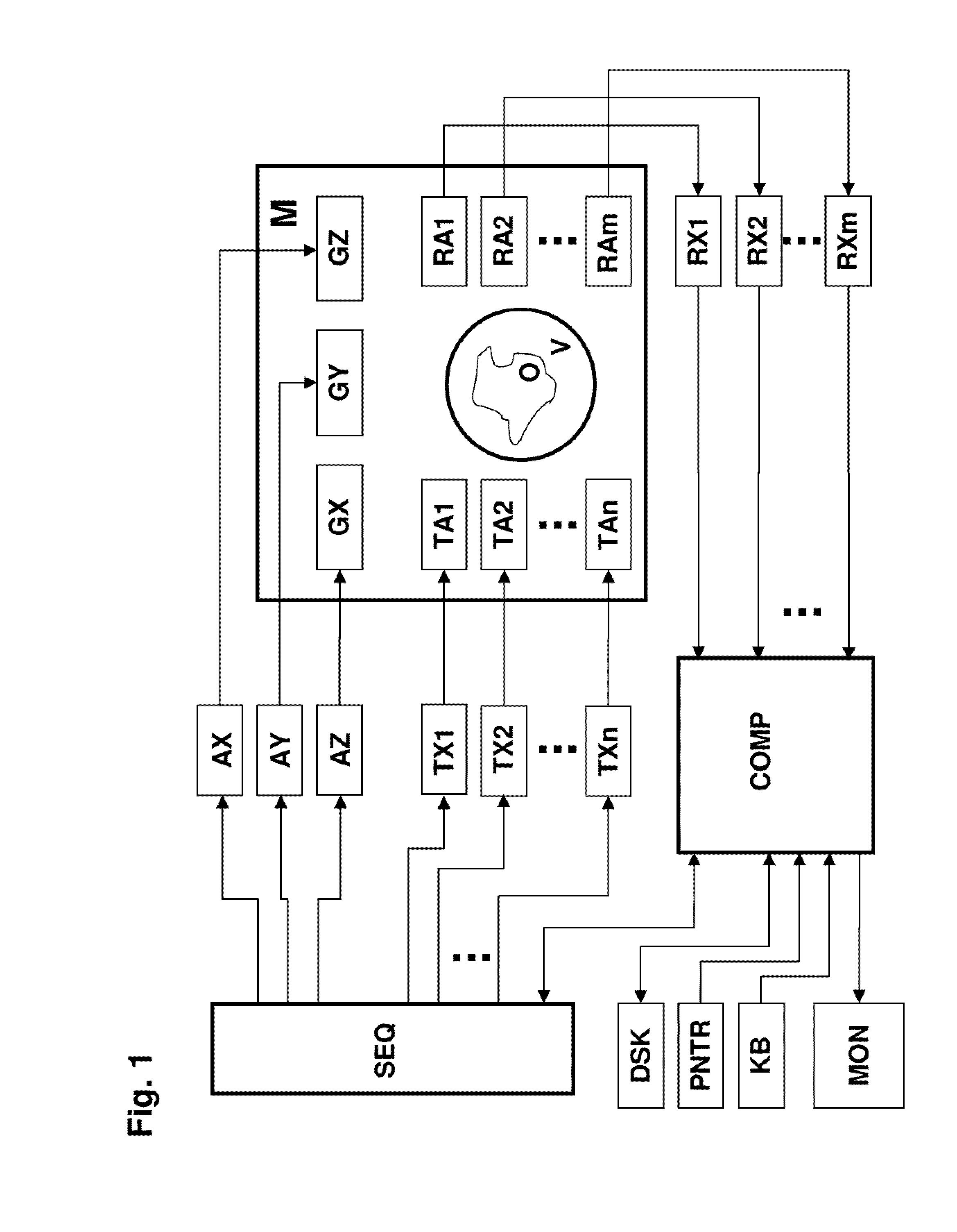
[0072]FIG. 1 schematically shows an MR measuring system which is suited for performing the inventive method. The system contains a main magnet M for generating the basic magnetic field which is substantially homogeneous and static in a volume under investigation V. Three sets of gradient coils GX, GY, and GZ are introduced into the bore of the main magnet M, which surround the volume under investigation V, and can superpose additional magnetic fields of controllable duration and strength with constant gradients on the basic field. Gradient amplifiers AX, AY, and AZ, which are driven by a sequence control unit SEQ for timely generation of gradient pulses, provide the gradient coils GX, GY, GZ with electric current for generating substantially linear gradient fields.

[0073]Several transmitting elements TA1 to TAn are located in the gradient field system, the entirety of which is also called transmitting antenna means. They surround an object under investigation O and are fed by several...


PUM


Abstract

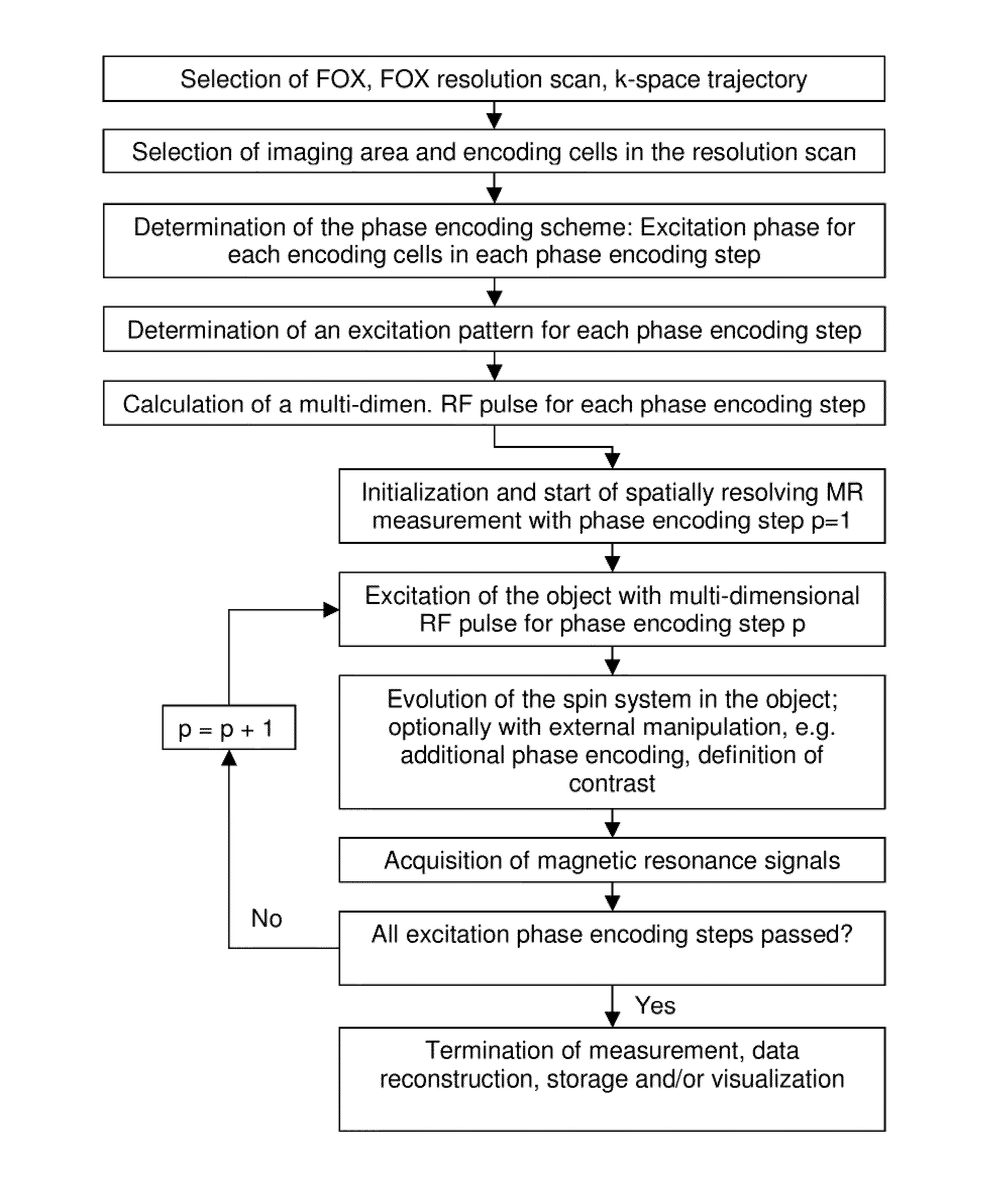
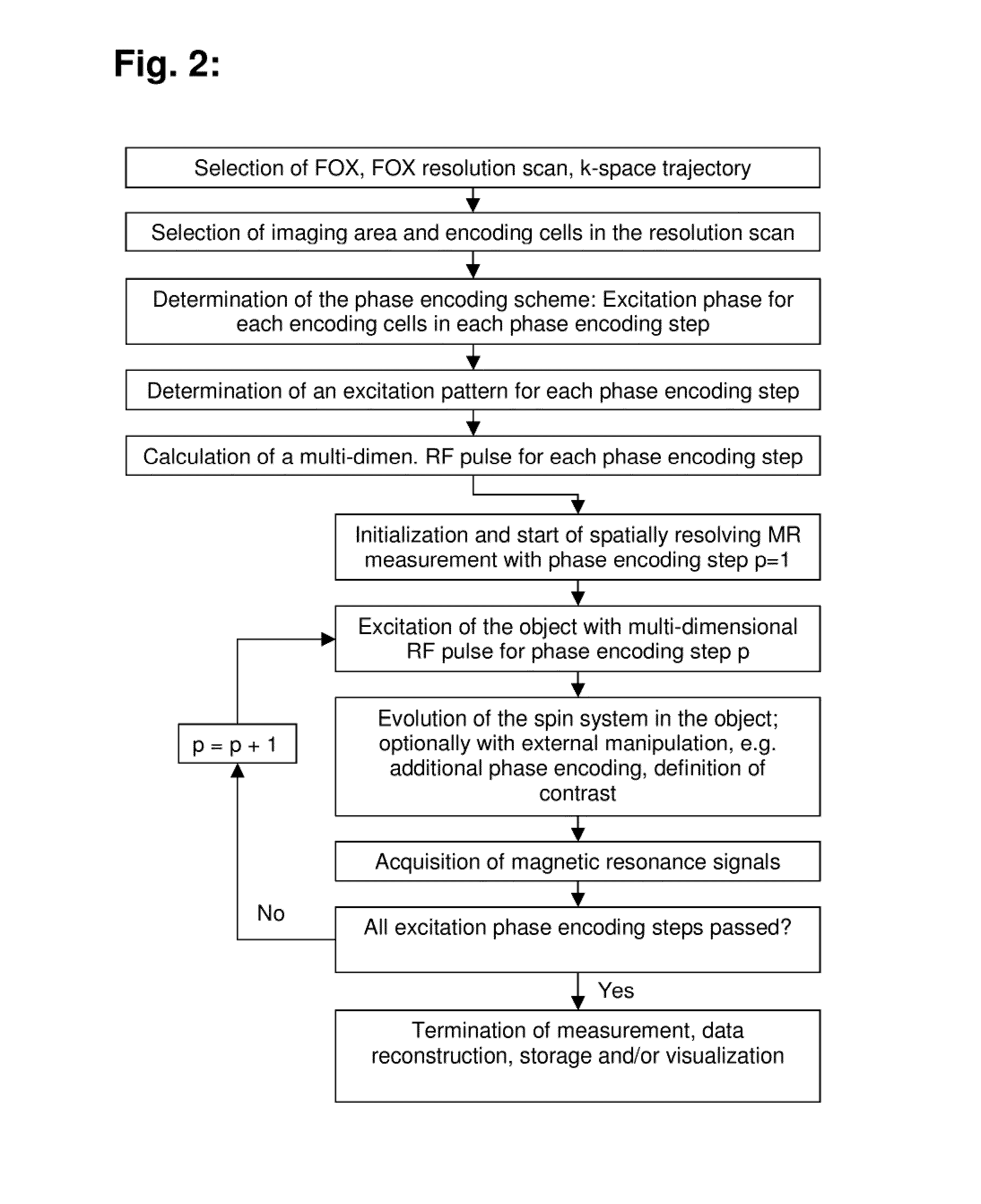
A method for determining the spatial distribution of magnetic resonance signals from an imaging area, wherein nuclear spins are excited in a spatially encoded fashion through multi-dimensional RF pulses, is characterized in that in a definition step, a resolution grid with resolution grid cells is predetermined, and in accordance with a predetermined phase encoding scheme, an excitation pattern is defined for each phase encoding step, in which the amplitudes within the imaging area are set in accordance with a predetermined distribution identically for each phase encoding step. In a preparatory step, the amplitude and phase behavior of the RF pulses to be irradiated is calculated in accordance with a predetermined k-space trajectory for each defined complex excitation pattern.

Description

[0001]This application is the national stage of PCT / EP2008 / 007617 filed on Sep. 13, 2008 and also claims Paris Convention priority to DE 10 2007 044 463.1 filed Sep. 28, 2007.BACKGROUND OF THE INVENTION[0002]The invention concerns a method for determining the spatial distribution of magnetic resonance signals from a predetermined imaging area that consists of at least one extended and interrelated region within a volume under investigation of a nuclear magnetic resonance apparatus, wherein nuclear spins are excited by multi-dimensional RF-pulses using magnetic field gradients and an RF transmitting antenna means with at least one transmitting element, wherein[0003]in a definition step, a k-space trajectory, which is to be generated through magnetic field gradient switching and passed through during excitation, and a phase encoding scheme with phase encoding steps are determined for spatial encoding,[0004]in a preparatory step, the amplitude and phase behavior with time of the RF pul...

Claims


Application Information

Patent Timeline
Patent Type & Authority Patents(United States)
IPC IPC(8): G01R33/54G06F19/00
CPCG01R33/4824G01R33/4833G01R33/4836G01R33/561G01R33/446
Inventor RUHM, WOLFGANG
Owner BRUKER BIOSPIN MRI
Learn More