Apparatus and method for the manufacture of a three-dimensional object

a three-dimensional object and apparatus technology, applied in the direction of ion implantation coating, chemical vapor deposition coating, coating, etc., can solve the problems of measurement results which may be falsified, the optical system of the ir camera might become dirty in the apparatus, and the temperature thus measured does not represent the temperature of the surface of the powder, so as to reduce the risk of damage, improve the utilization of the building field, and the effect of easy blowing

Inactive Publication Date: 2012-03-20
EOS ELECTRO OPTICAL SYST
View PDF26 Cites 131 Cited by
  • Summary
  • Abstract
  • Description
  • Claims
  • Application Information

AI Technical Summary

Benefits of technology

[0007]The invention has the particular advantage that the temperature of the building material to be solidified can be measured and, thus, controlled and/or regulated in a highly precise manner without being affected by the radiation energy introduced for solidification into the building material by electromagnetic radiation or particle radiation.
[0008]Furthermore, the invention has the advantage that a simple and. cost-effective point pyrometer can be used for temperature measurement wherein, contrary to an IR camera, said point pyrometer does not require any cooling. Moreover, the window required in the process chamber for the point pyrometer is considerably smaller than that required for an IR camera. A small window can, in turn, be kept free from any dirt caused by process gas much more easily by blowing and it reduces the risk of damage to the temperature measuring assembly by laser retroreflection, when a laser is used as the source of radiation.
[0009]Furthermore, the invention has the advantage that the measuring region can be selected, that

Problems solved by technology

For that reason, the temperature thus measured does not represent a good measure for the temperature of the surface of the powder. bed.
One problem is that the optical system of the IR camera might become dirty in the apparatus.
This dirt, which cannot be avoided entirely by blowi

Method used


Image

  • Apparatus and method for the manufacture of a three-dimensional object
  • Apparatus and method for the manufacture of a three-dimensional object
  • Apparatus and method for the manufacture of a three-dimensional object

Examples


first embodiment

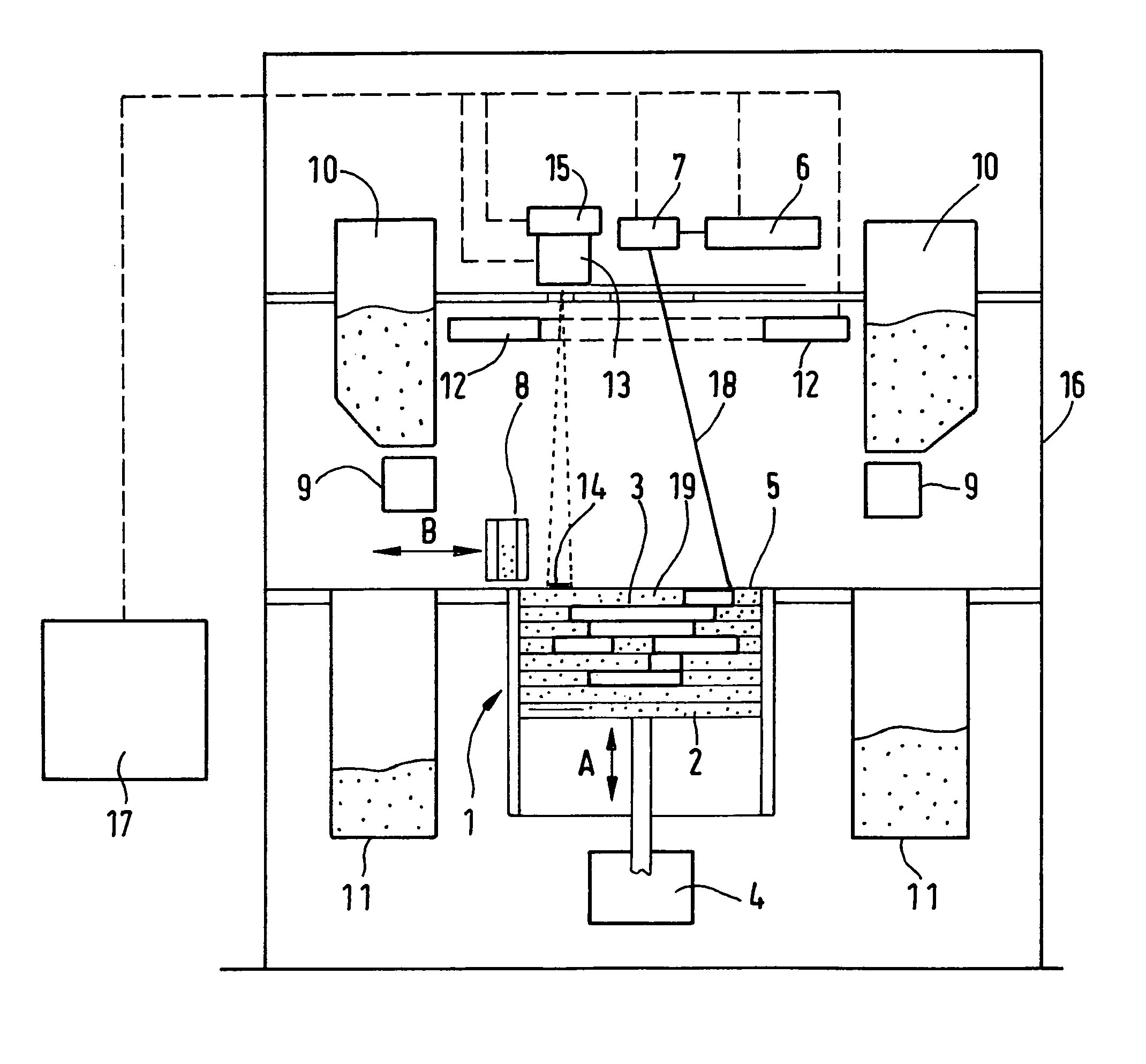
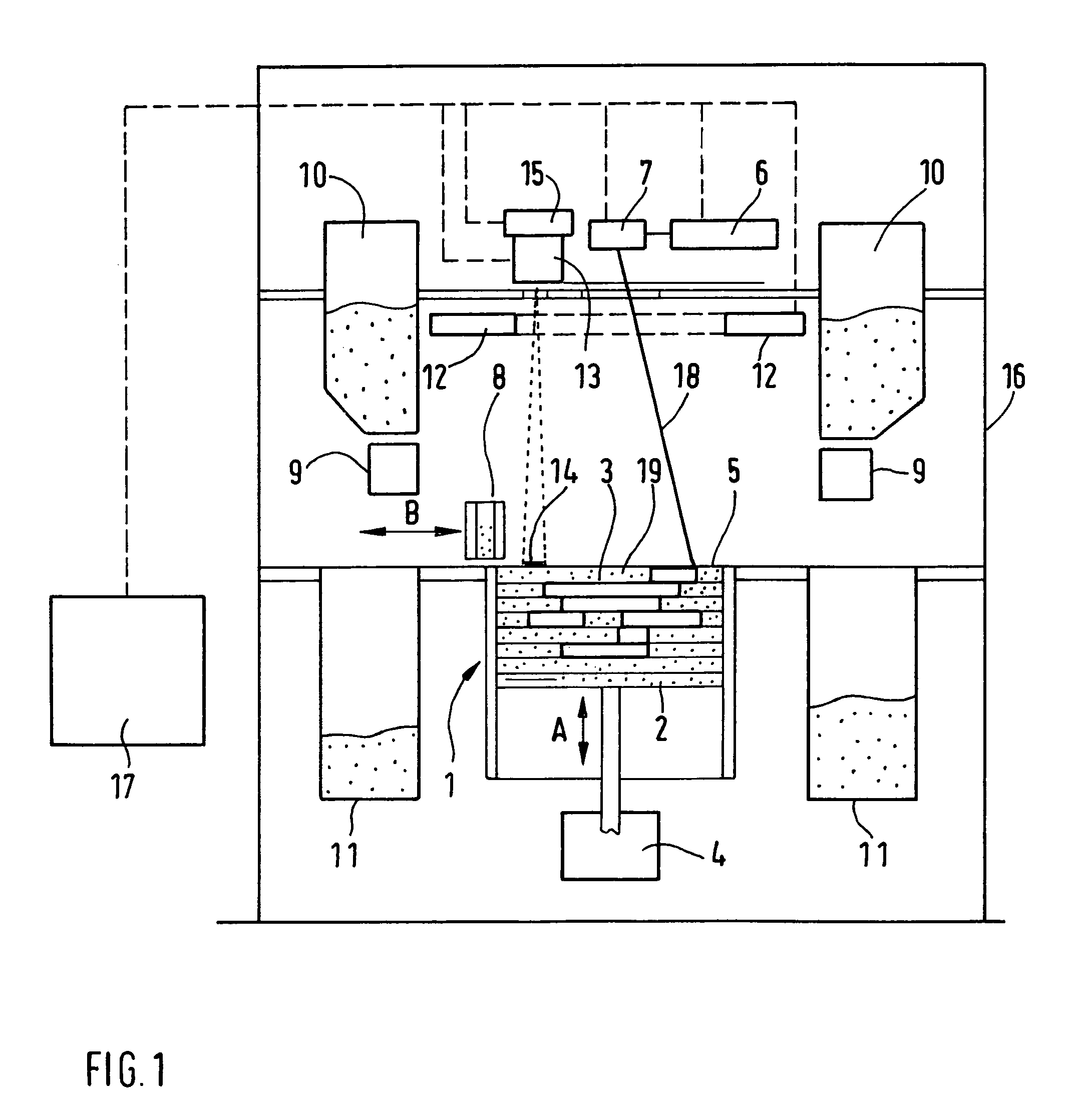
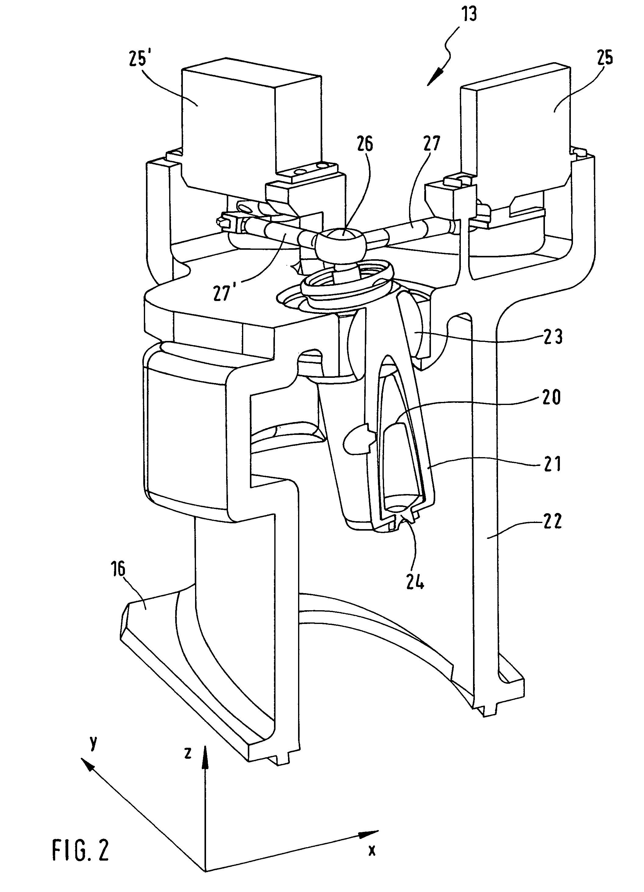
[0028]To achieve this, the temperature of the powder layer, after the latter has been applied, is measured by means of the temperature measuring assembly 13 in a non-contact manner. The heat output of the heating device 12 is determined in relation to the temperature measured. Therein, the position of the measurement region 14 of the temperature measuring assembly 13 is adjusted by means of the position adjustment device 15 such that the measurement region 14 will not overlap with a region 30 in the layer, which is solidified in the following step by irradiating it with the laser. Hence, when the method is utilized, a region not to be exposed is actively accessed in each layer before said layer solidifies, in order to measure the temperature of the surface of the uppermost powder layer.

[0029]In the first embodiment, the measurement region is, preferrably, selected such that it is spaced apart from the regions in the layer, which are to be exposed, as well as from imaged regions in ...

second embodiment

[0034]In the method according to the invention, the position of the measurement region is also changed during the exposure. As a result, the temperature in a layer is measured at different positions so that a temperature distribution is measured.

[0035]The temperature distribution of the surface of the powder layer thus measured is used by the control device 17 for controlling the energy introduced by the laser radiation by controlling the local laser power of the irradiation assembly 6 and / or by controlling the scanning speed used by the deflection device 7 to move the directed laser beam across the building field during the exposure.

[0036]As in the first embodiment, the position of the measurement region in a layer is altered and / or adjusted independently of any change of the position of the beam spot region.

[0037]The method according to the invention corresponding to the second embodiment has the advantage that the measurement of the temperature distribution in the layer allows to...


PUM

PropertyMeasurementUnit
Temperatureaaaaaaaaaa
Distanceaaaaaaaaaa

Abstract

Provision is made of an apparatus and a method for the manufacture of three-dimensional objects (3) by local solidification of layers of a building material at positions corresponding to the respective cross-section of the object (3), by exposure to electromagnetic or particle radiation. The apparatus comprises a temperature measuring assembly (13) for non-contact measurement of the temperature of the building material in a measurement region (14) which is a partial region of the layer of the building material, and comprises further a position adjustment device (15) for altering the position of the measurement region (14) of the temperature measuring assembly (13) independently of the alteration of the position of the region exposed to the radiation energy. This apparatus can be used to actively access a not exposed region of the surface for measuring the temperature of each layer and to detect a temperature distribution by altering the position of a measurement region (14) in a layer.

Description

FIELD OF THE INVENTION[0001]The present invention relates to an apparatus and a method for the manufacture of a three-dimensional object according to the preamble of claims 1 and 10 respectively.BACKGROUND OF THE INVENTION[0002]Such an apparatus and such a method are known from DE 100 07 711 C1. There, a laser sintering apparatus is described wherein the temperature of the sinter powder in a moving detection area in the region of the sintering position is detected by means of a pyrometer and wherein the power of the laser is regulated in relation to the temperature detected.[0003]Therein, the thermal radiation of the sintering position has a considerable influence on the temperature measured by the pyrometer. Depending on the degree of exposure of the powder, the emission capability of the surface is changing (ratio of the radiation energy emitted by the surface to the radiation energy emitted by a black body at the same temperature), thus falsifying the measurement result. Furtherm...

Claims


Application Information

Patent Timeline
IPC IPC(8): C23C16/52
CPCB29C67/0077B29C35/0288B29C64/153B33Y10/00B33Y30/00Y02P10/25
Inventor PHILIPPI, JOCHENHALDER, THOMASMATTES, THOMAS
Owner EOS ELECTRO OPTICAL SYST
Why Eureka
Try Eureka