

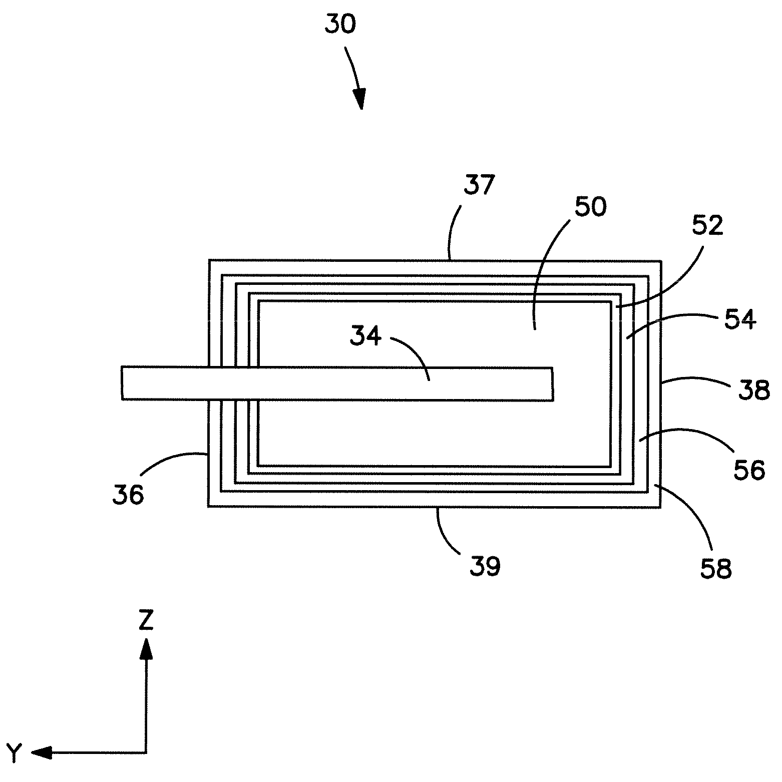
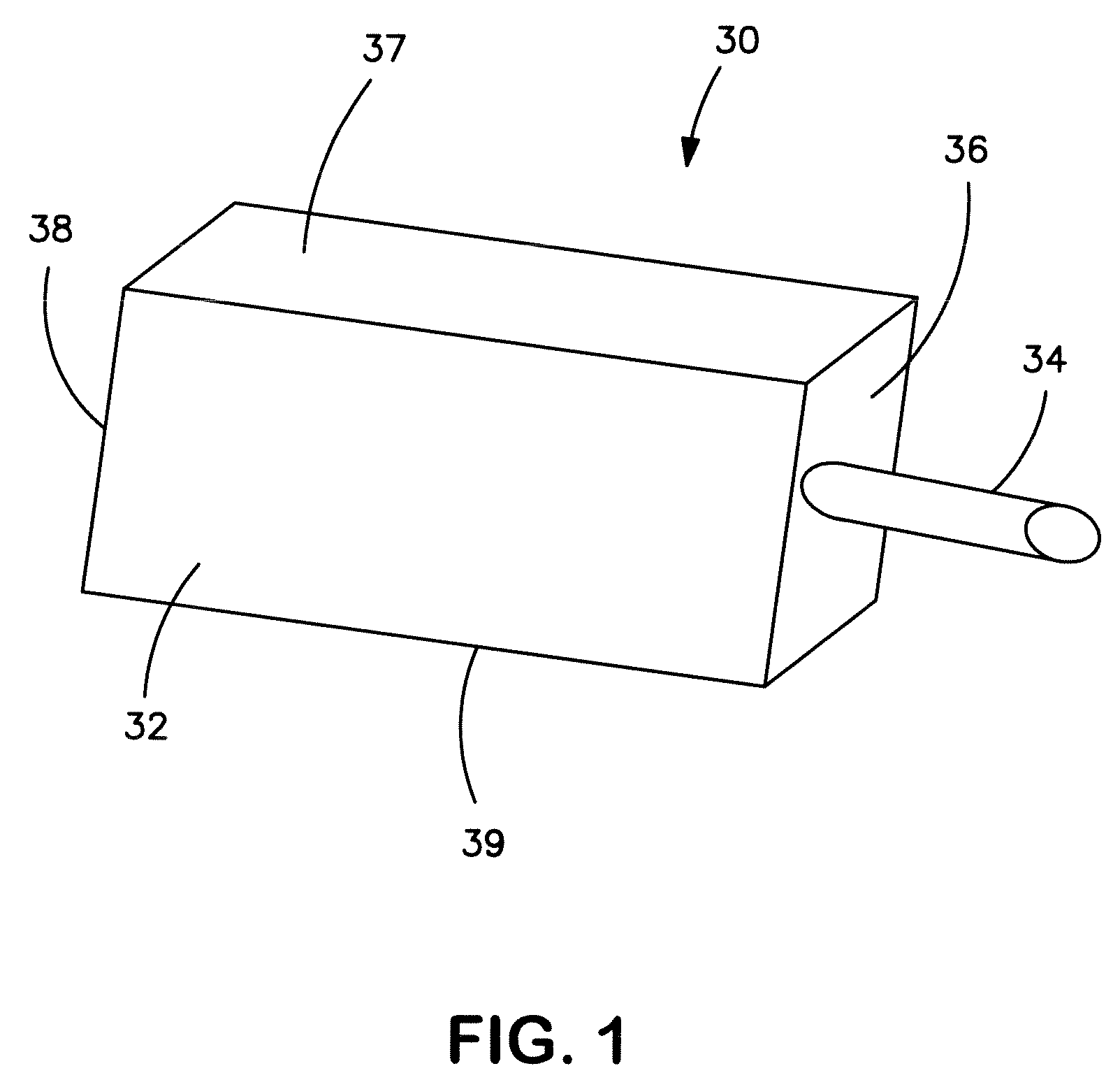
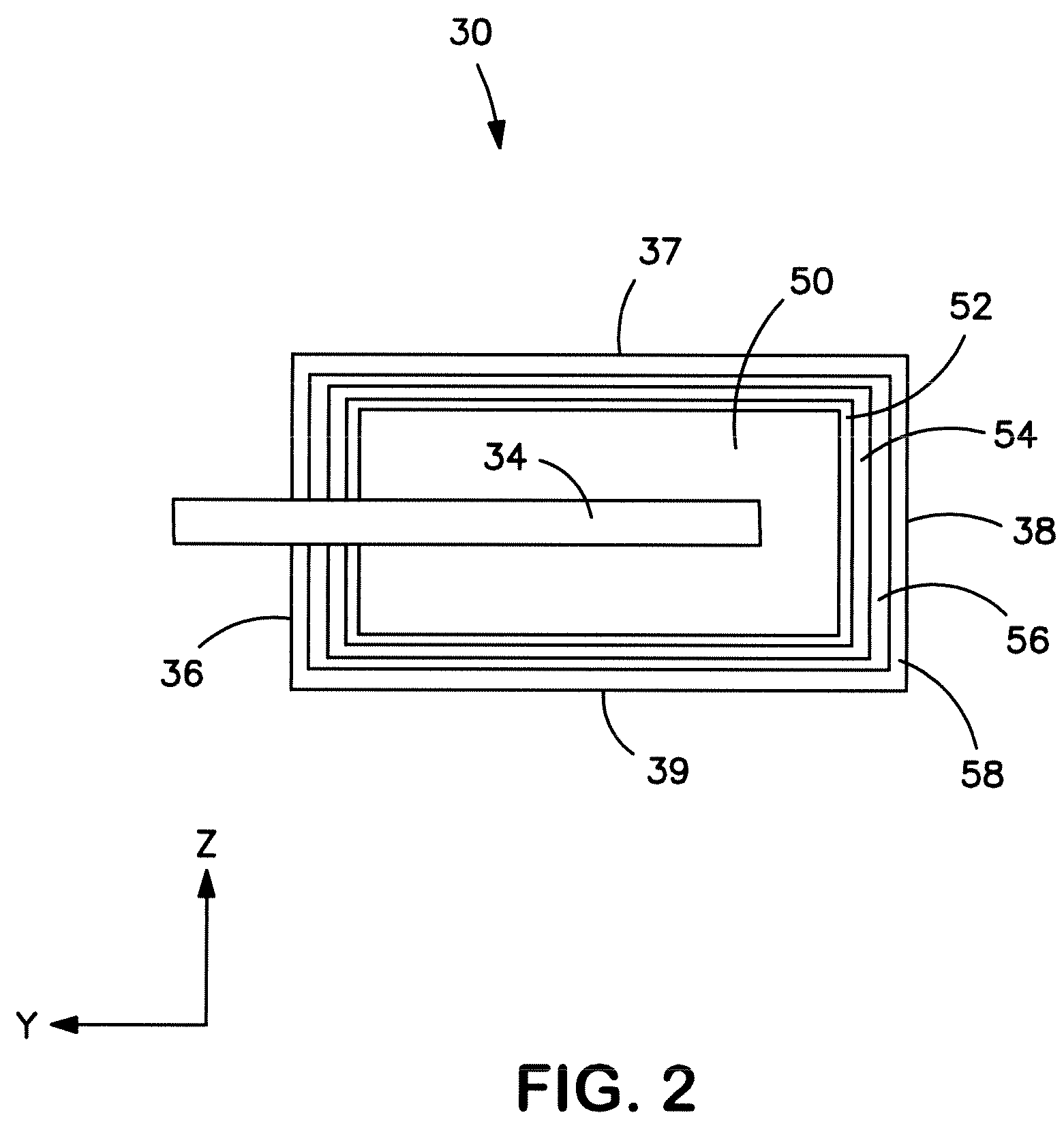
Anode for a solid electrolytic capacitor containing a non-metallic surface treatment
a solid electrolytic capacitor and surface treatment technology, applied in the field of anodes, can solve the problems of capacitor damage or destruction, affecting the rated voltage of capacitors, and affecting the use of high-voltage applications,
- Summary
- Abstract
- Description
- Claims
- Application Information
AI Technical Summary
Benefits of technology
Problems solved by technology
Method used
Image

Examples
example 1
[0052]NbO powder (HC Starck, 80,000 μF*V / g) was initially embedded with a tantalum lead wire and pressed on a top / bottom press machine to a density of 3.4 g / cm3. The binder was then removed by placing the pellet into a nitrogen atmosphere at a temperature of 400° C. to 500° C. The pellet was then sintered at a temperature of 1520° C. for 10 minutes in an argon atmosphere. After sintering, two samples (Samples Nos. 1-2) of the NbO anodes were wetted in a solution containing 14 wt. % H3PO4 for 1 minute (decant), dried at a temperature of 100° C. for 2 hours, and then baked at a temperature of 245° C. for 30 minutes. For Sample No. 2, these steps were repeated two (2) times.
[0053]To anodize the anodes, they were dipped into a weak phosphoric acid / water solution having a conductivity of 8.6±0.3 mS / cm and temperature of 85±5° C., applied with a voltage of 65V and current higher than 100 mA / g, and washed with deionized water. The entire part was then applied with a manganese dioxide catho...
example 2
[0057]NbO powder (HC Starck, 80,000 μF*V / g) was initially embedded with a tantalum lead wire and pressed on a top / bottom press machine to a density of 3.4 g / cm3. The binder was then removed by placing the pellet into a nitrogen atmosphere at a temperature of 400° C. to 500° C. The pellet was then sintered at a temperature of 1520° C. for 10 minutes in an argon atmosphere. After sintering, three samples (Samples Nos. 3-5) of the NbO anodes were wetted in a solution containing 14 wt. % H3PO4 for 1 minute (decant), dried at a temperature of 100° C. for 2 hours, and then baked at a temperature of 245° C. for 30 minutes. For Sample Nos. 4 and 5, these steps were repeated two (2) times and five (5) times, respectively.
[0058]To anodize the anodes, they were dipped into a weak phosphoric acid / water solution having a conductivity of 8.6±0.3 mS / cm and temperature of 85±5° C., applied with a voltage of 12.5V and current higher than 100 mA / g, and washed with deionized water. The entire part was...
example 3
[0062]NbO powder (HC Starck, 80,000 μF*V / g) was initially embedded with a tantalum lead wire and pressed on a top / bottom press machine to a density of 3.4 g / cm3. The binder was then removed by placing the pellet into a nitrogen atmosphere at a temperature of 400° C. to 500° C. The pellet was then sintered at a temperature of 1520° C. for 10 minutes in an argon atmosphere. After sintering, a sample (Samples No. 6) of the NbO anodes were wetted in a solution containing 2.3 wt. % H3PO4 for 1 minute (decant), dried at a temperature of 100° C. for 2 hours, and then baked at a temperature of 245° C. for 30 minutes. These steps were repeated five (5) times.
[0063]To anodize the anodes, they were dipped into a weak phosphoric acid / water solution having a conductivity of 8.6±0.3 mS / cm and temperature of 85±50° C., applied with a voltage of 65V and current higher than 100 mA / g, and washed with deionized water. The entire part was then applied with a manganese dioxide cathode layer as is known ...
PUM
| Property | Measurement | Unit |
|---|---|---|
| temperature | aaaaa | aaaaa |
| wt. % | aaaaa | aaaaa |
| wt. % | aaaaa | aaaaa |
Abstract
Description
Claims
Application Information