Hollow-core photonic crystal fibre

a photonic crystal fibre and hollow core technology, applied in the direction of paper/cardboard containers, lamination, containers, etc., can solve the problems of small pitch required, difficult to accurately control small pitch, and hcpcfs of small pitch triangular lattices

Active Publication Date: 2012-11-06
GLOPHOTONICS
View PDF14 Cites 40 Cited by
  • Summary
  • Abstract
  • Description
  • Claims
  • Application Information

AI Technical Summary

Benefits of technology

[0012]According to one aspect, a HCPCF with a pitch five or more times larger than the wavelength of operation (a ‘large’ pitch) is provided. Such an HCPCF has various surprising optical properties. The mechanism by which the fibre guides removes some of the limitations present with currently known HCPCFs. The fibre possesses transmission regions at high normalized frequency (˜20<kΛ<400). The fibre exhibits a broad transmission region, which may be, for example, twenty times larger than that of the known triangular HCPCF discussed above, with relatively low loss. The fibre is relatively easy to fabricate and shows low surface mode coupling, a high light-in-core fraction and low chromatic dispersion.
[0013]According to another aspect, a HCPCF with a transverse structure comprising relatively thin (<5% and preferably <3% of the pitch Λ) portions of cane cladding walls connecting nodes is provided, so that the physical size of the low refractive index cladding structure constituent (e.g. air) approaches that of the pitch whilst the physical thickness of the high index cladding structure constituent (e.g. silica) is only 3% or less of the pitch. Such a HCPCF has improved optical properties because minimising the thickness of the connecting walls means that fewer cladding modes are present for the fibre and the nature of the supported modes means that they interact little with those of the core.
[0016]Further, in addition or alternatively, etching of canes forming the cladding with liquid HF based etchant also enables control of wall thickness meaning the thickness of the wall obtained can be controlled and a desired wall thickness can be obtained and The above-described HCPCF structure having relatively thin connecting walls is obtainable using this manufacturing method.

Problems solved by technology

The fabrication of such HCPCFs poses several engineering challenges.
Secondly, the core mode couples with interface modes located at the core surround, which affects the guidance dramatically.
Thirdly, the small pitch required is difficult to control accurately during the fibre drawing process.
Because of the manufacturing techniques used (conventionally, capillaries are blown and then etched with a gas such as gaseous hydrogen fluoride (HF)), these small pitch triangular lattice HCPCFs also suffer from the problem that their optical properties are not optimum, for example because undesired modes may be present.
These issues inherent to fabricating visible and UV guiding HCPCFs and the overlapping of guided light with silica limit their loss (optical attenuation) to about 1 dB / m.
As well as the fabrication difficulties, there are also other drawbacks that prevent such triangular lattice fibres from being used in applications requiring broadband guidance or guidance in the visible or UV.

Method used


Image

  • Hollow-core photonic crystal fibre
  • Hollow-core photonic crystal fibre
  • Hollow-core photonic crystal fibre

Examples


Embodiment Construction

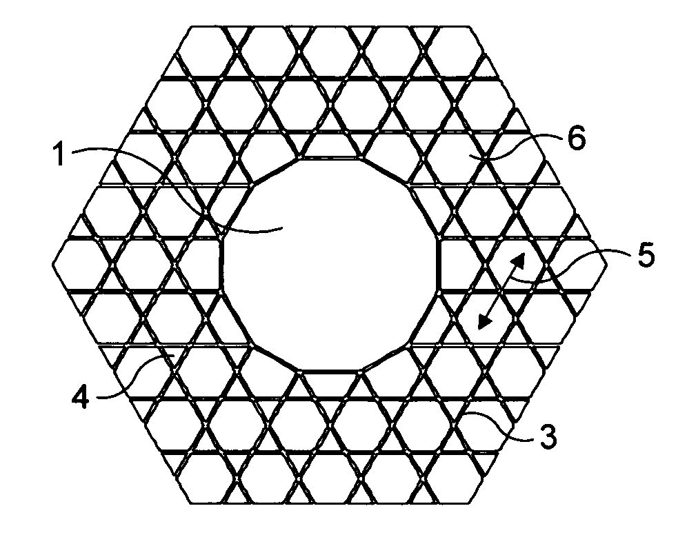
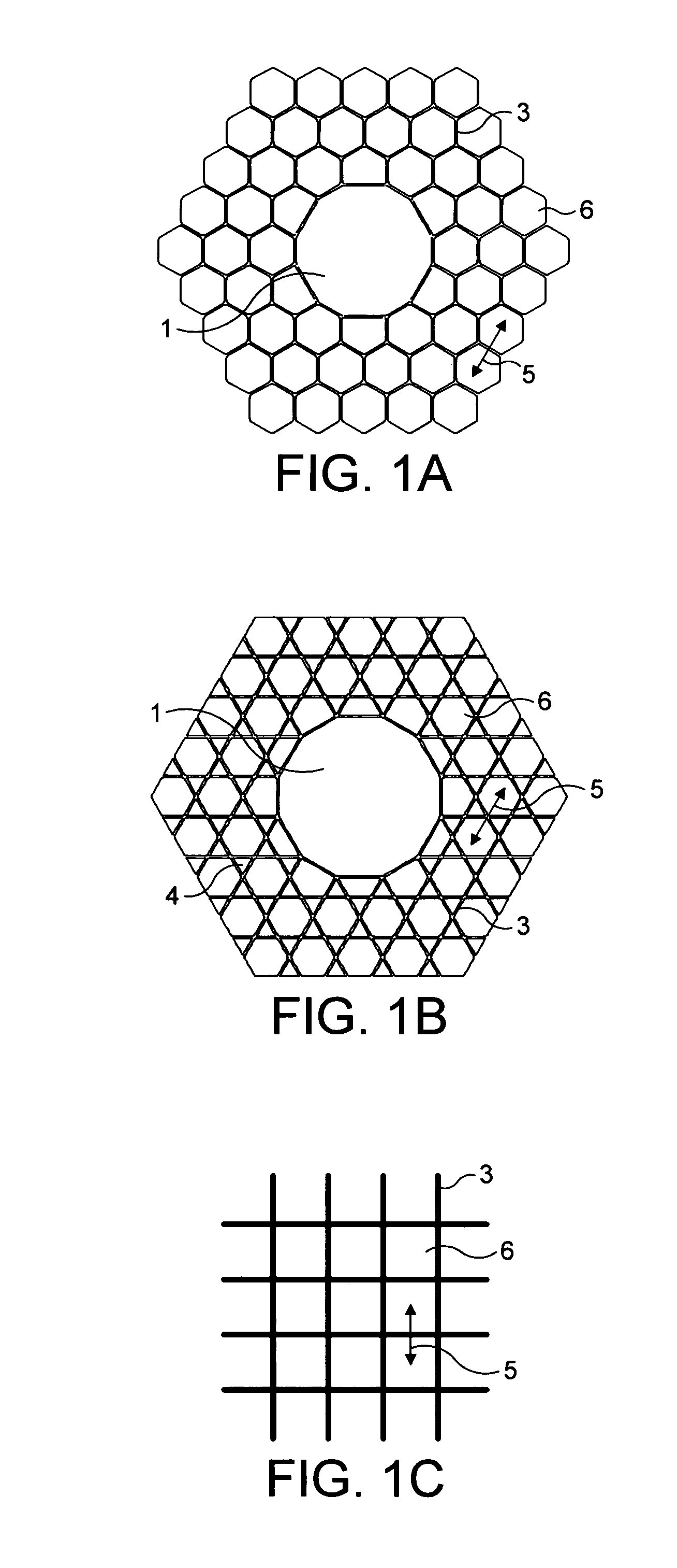
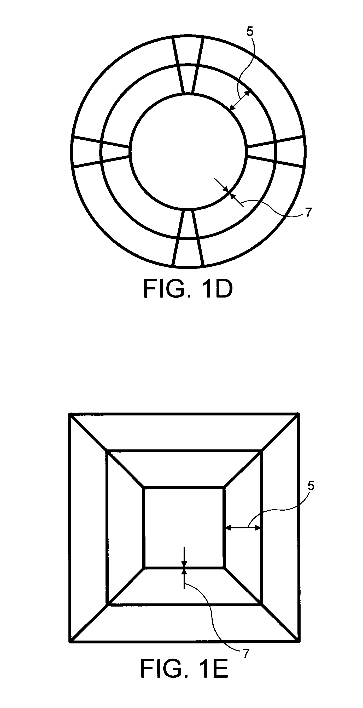
[0030]In overview, a first disclosed fibre is a HCPCF with a transverse structure with a pitch at least five times larger than the wavelength of operation. HCPCF may also be known as band-gap fibre, air-guiding band-gap fibre, or microstructure fibre. The term HCPCF as used herein is understood to cover all such alternative terminologies, which will be familiar to the skilled reader. The HCPCF has a hollow core 1 (see also FIG. 3) surrounded by a cladding 2 of silica microcapillaries 3. By ‘transverse’ it is meant the direction perpendicular to the waveguide direction. The waveguide direction is the direction of the length of the holes 6 in the capillaries 3. As shown in FIG. 1, the pitch of a fibre is the distance 5 between centres of the holes 6 in the capillaries 3.

[0031]The example cladding structure shown in FIG. 1B is a kagome structure with a Star of David arrangement, where in the main body of the cladding 2, the microcapillaries 3 have an approximately hexagonal perimeter, ...


PUM

PropertyMeasurementUnit
infra-red (IR) wavelengthaaaaaaaaaa

Abstract

A hollow core photonic crystal fiber (HCPCF) having a wavelength of operation, the HCPCF comprising: a core region having a first refractive index; a cladding region surrounding the core region and comprising a plurality of microcapillaries arranged in a transverse structure having a pitch, the pitch of the structure being at least five times larger than the wavelength of operation, the cladding region having a second refractive index higher than the first refractive index.

Description

BACKGROUND[0001]1. Field[0002]The present invention relates to a hollow-core photonic crystal fibre (HCPCF) with a large pitch. By “large pitch” it is meant that the photonic structure has a pitch of a size of the order of five times or more as large as the wavelength of light at which the HCPCF operates. The present invention also relates to a HCPCF with a transverse structure comprising relatively thin connecting microcapillary walls. The present invention further relates to methods of manufacturing an HCPCF.[0003]2. Background Art[0004]A currently known HCPCF has a hollow core surrounded by a cladding of silica microcapillaries and creates a photonic band gap (PBG), trapping in the core defect electromagnetic waves within a particular range of optical wavelengths. HCPCFs are theoretically designed around two balancing factors: the need for a large PBG at the wavelength of interest and the feasibility of manufacturing the fibre with the methods available. Out of all known cladding...

Claims


Application Information

Patent Timeline
Patent Type & Authority Patents(United States)
IPC IPC(8): G02B6/032
CPCC03B37/0122C03B37/02781G02B6/02328G02B6/02347C03B2203/14C03B2203/16Y10T156/10G02F1/365G02F2201/02C03B2203/42
Inventor BENABID, ABDEL FETAHCOUNY, FRANCOIS YVES MICHEL DENISROBERTS, PETER JOHN
Owner GLOPHOTONICS
Why Eureka
Try Eureka