Plasma cleaning method and plasma CVD method

a cleaning method and plasma technology, applied in the field of plasma cleaning method and plasma cvd method, can solve the problems of insufficient studies concerning the conditions of performing the cleaning process at high throughput to achieve the cleaning effect practically sufficient, adversely affect the film formation performed in the plasma cvd apparatus, and deteriorate the film formation rate and/or film formation uniformity, etc., to achieve the effect of improving the uniformity of the plasma cvd process, high throughput and high throughpu

Active Publication Date: 2013-02-05
TOKYO ELECTRON LTD
View PDF23 Cites 77 Cited by
  • Summary
  • Abstract
  • Description
  • Claims
  • Application Information

AI Technical Summary

Benefits of technology

[0007]An object of the present invention is to provide a plasma cleaning method that can reliably decrease residual fluorine at high throughput.
[0008]Another object of the present invention is to provide a plasma cleaning method that allows the endpoint of cleaning to be easily found and can suppress plasma damage to components inside a chamber to the minimum.
[0022]The present invention comprises supplying a cleaning gas containing NF3 gas into a process container and generating plasma thereof, thereby removing extraneous deposits, and then supplying a gas containing hydrogen gas into the process container and generating plasma thereof, thereby removing residual fluorine. With this arrangement, residual fluorine in the plasma CVD process container is reliably decreased at high throughput, and the film formed on the substrate is prevented from being contaminated with fluorine.
[0023]Further, where plasma light emission is monitored to perform endpoint detection for each of the extraneous deposit removing stage, fluorine removing stage, and hydrogen removing stage, the time periods of the stages can be properly managed. Consequently, plasma damage due to a plasma process excessively performed is suppressed to the minimum while the cleaning is performed at high throughput.
[0024]Further, where the plasma cleaning method is incorporated into a plasma CVD process for forming a silicon nitride film in the process of manufacturing various semiconductor devices, the chamber is prevented from falling into a state with excessive extraneous deposits formed therein. Consequently, the uniformity of the film formation in the plasma CVD process is improved, while particle generation is suppressed to the minimum, so that the process can be continuously and stably performed on respective target substrates.

Problems solved by technology

If extraneous deposits thus formed on portions inside the chamber exceed a certain film thickness, the film formation performed in the plasma CVD apparatus is adversely affected.
For example, the extraneous deposits formed on portions inside the chamber affect gas flows and / or thermal distribution inside the chamber, and may deteriorate the film formation rate and / or film formation uniformity.
However, where a fluorine-containing gas, such as NF3 gas, is used for cleaning, it is necessary to remove residual fluorine inside the chamber because the residual fluorine adversely affects a film formation process subsequently performed.
The technique disclosed in Jpn. Pat. Appln. KOKAI Publication No. 7-201738 described above is arranged to use a stage of removing residual fluorine inside the chamber after NF3 cleaning, but cannot be said to involve sufficient studies concerning conditions for performing the cleaning process at high throughput to swiftly remove residual fluorine while attaining a cleaning effect practically sufficient.
Further, where a cleaning process includes a plurality of stages, as in the technique described above, it is difficult to find the endpoints of the respective stages.
If the cleaning is excessively performed due to erroneous determination of the endpoints, plasma of a cleaning gas etches members inside the chamber, such as a worktable (susceptor) for placing a target substrate thereon and a cover ring for guiding the target substrate, and causes plasma damage thereon, which shortens the service life of the members.
Particularly, if the cleaning is performed for a longer time to enhance the cleaning effect, the plasma damage becomes larger and thereby deteriorates the throughput.
In reverse, if conditions are set to suppress the plasma damage and thereby increase the throughput, cleaning becomes insufficient, thereby generates particles, and adversely affects the film formation.

Method used


Image

  • Plasma cleaning method and plasma CVD method
  • Plasma cleaning method and plasma CVD method
  • Plasma cleaning method and plasma CVD method

Examples


Embodiment Construction

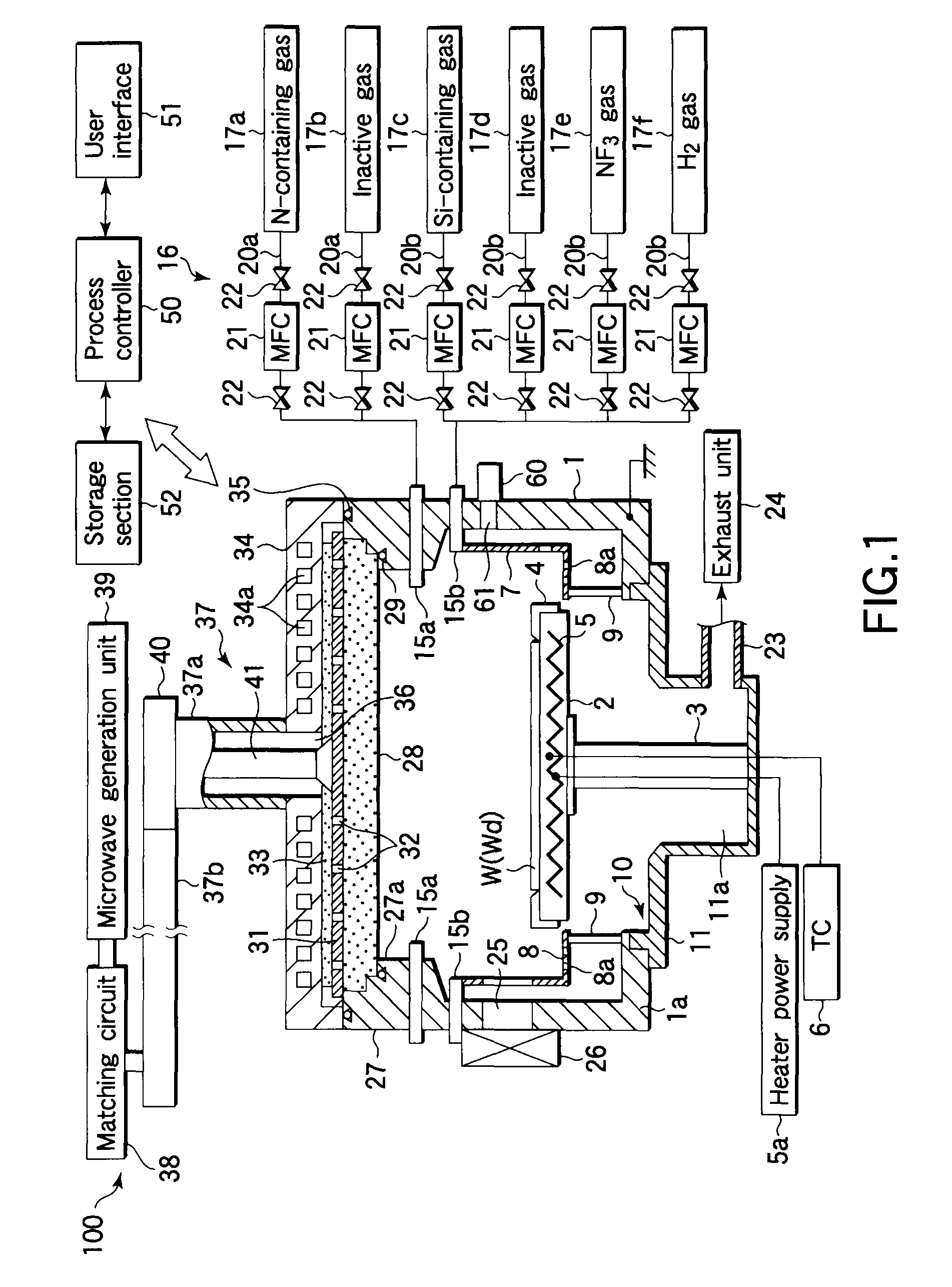
[0035]An embodiment of the present invention will now be described in detail with reference to the accompanying drawings. FIG. 1 is a sectional view schematically showing an example of a plasma processing apparatus suitable for performing a plasma cleaning method and a plasma CVD method according to the present invention. This plasma processing apparatus 100 is arranged as a processing apparatus of the RLSA (Radial Line Slot Antenna) microwave plasma type, in which microwaves are supplied from a planar antenna having a plurality of slots into a process chamber to generate plasma. In this case, microwave excitation plasma is generated with a high density and a low electron temperature, such as a plasma density of 1×10¹⁰ to 5×10¹² / cm3 and a low electron temperature of 0.7 to 2 eV, and so a process can be performed with very little damage to the film. Accordingly, apparatuses of this type are preferably utilized for processes, such as formation of a silicon nitride film by plasma CVD, ...


PUM

PropertyMeasurementUnit
temperatureaaaaaaaaaa
inner pressureaaaaaaaaaa

Abstract

A plasma cleaning method is performed in a plasma CVD apparatus for depositing a silicon nitride film on a surface of a target substrate, and includes a stage (S1) of supplying a cleaning gas containing NF3 gas into a process container, thereby removing extraneous deposits formed on portions inside the process container; a stage (S2) of supplying a gas containing hydrogen gas into the process container and generating plasma thereof, thereby removing residual fluorine inside the process container; and a stage (S3) of supplying a gas containing a rare gas into the process container and generating plasma thereof, thereby removing residual hydrogen inside the process container.

Description

TECHNICAL FIELD[0001]The present invention relates to a plasma cleaning method for cleaning the interior of a process container of a plasma CVD (Chemical Vapor Deposition) apparatus that is used for depositing a silicon nitride film on the surface of a target substrate, and also relates to a plasma CVD method.BACKGROUND ART[0002]Silicon nitride films are used as insulating films, protection films, and so forth in various semiconductor device. It is known that a silicon nitride film of this kind can be formed by plasma CVD or the like using a silicon-containing compound gas, such as silane (SiH4), as a source gas and a nitrogen-containing compound gas, such as nitrogen or ammonia.[0003]In a plasma CVD apparatus for performing plasma CVD as described above, as the film formation is repeated on target substrates, silicon nitride is deposited on portions inside the chamber other than the target substrates. If extraneous deposits thus formed on portions inside the chamber exceed a certai...

Claims


Application Information

Patent Timeline
Patent Type & Authority Patents(United States)
IPC IPC(8): B44C1/22G01L21/30G01R31/00C03C15/00H01L21/302H01L21/461
CPCC23C16/4405H01L21/3185H01J37/32862H01L21/02274H01L21/02211H01L21/0217H01L21/31H01L21/3065H05H1/46
Inventor KOHNO, MASAYUKINISHITA, TATSUONAKANISHI, TOSHIO
Owner TOKYO ELECTRON LTD
Why Eureka
Try Eureka