Exhaust emission control device for internal combustion engine

a technology for exhaust and combustion engines, applied in electrical control, machines/engines, separation processes, etc., can solve the problems of deteriorating fuel economy, increasing the amount of nox discharging from the lnt along with the increase of nox emission amount, and reducing the efficiency of exhaust recirculation, so as to reduce the time consumed in the sox regeneration process and maximize the exhaust recirculation ratio

Inactive Publication Date: 2013-05-07
HONDA MOTOR CO LTD
View PDF33 Cites 24 Cited by
  • Summary
  • Abstract
  • Description
  • Claims
  • Application Information

AI Technical Summary

Benefits of technology

[0056]An object of the present invention is to provide an exhaust purification device of an internal combustion engine that can prevent the NOx purification performance from declining depending on the operating state. In addition, concomitant with this, providing an exhaust purification device of an internal combustion engine that can stably execute a SOx regeneration process of the NOx purification catalyst irrespective of the operating state is also made an object of the present invention.Means for Solving the Problems
[0117]According to this configuration, in a case of the internal combustion engine performing so-called deceleration fuel-cut in a state in which the injection of fuel has been suspended with deceleration operation thereof, at least one among control to minimize the intake air amount and control to maximize the exhaust recirculation ratio is performed, and the exhaust air / fuel ratio is enriched by supplying reducing gas. This enables the exhaust air / fuel ratio of the exhaust flowing into the NOx purification catalyst to be maintained at or below the stoichiometric ratio while performing deceleration fuel-cut, and for the SOx regeneration process to be continued. Therefore, the time consumed in the SOx regeneration process can be further shortened and deterioration of the fuel economy can be reduced.

Problems solved by technology

However, there is the following problem in a case of repeating lean operation and rich operation of an engine as in the technology shown in Patent Documents 1 and 2 and Non-patent Documents 1 and 2 described above, for example.
In such a case, the NOx occluded to the LNT desorbs from the exhaust air / fuel ratio being made rich; however, it will be discharged downstream of the LNT without being reduced, and thus the NOx purification performance may decline.
In particular, since it is difficult to recirculate a great amount of exhaust during high-load operation in which there is a tendency for the emission amount of NOx to increase, the amount of NOx discharging from the LNT may increase along with an increase in the emission amount of NOx.
However, since fuel is injected into the cylinders in the latter half of the combustion stroke or in the exhaust stroke of the engine in the method by post rich, a portion of the fuel adheres to the cylinder walls.
As a result, the fuel economy may deteriorate compared to the method by combustion rich.
Moreover, with the method of combustion rich, the operating conditions thereof are limited.
For example, during high-load operation in which combustion becomes sharp, the combustion noise grows worse.
In addition, during low-load operation such as immediately after startup of the engine or while idling, the charge efficiency to the cylinders may decline and combustion may become unstable.
Alternatively, when rich operation is performed and the exhaust air / fuel ratio is made rich, although NOx occluded to the LNT desorbs, in a case in which the NOx occlusion amount of the LNT is large, NOx will be discharged downstream of the LNT without being reduced, and thus the NOx purification performance may decline.
However, the region in which rich operation can be performed is limited depending on the operation state of the engine such as revolution speed and torque.
As a result, it is difficult to reduce NOx frequently independently of the operating state of the engine.
However, in a case of purifying with LNT by adding a reducing agent such as hydrogen, carbon monoxide, and hydrocarbons into exhaust having an oxygen excess in such a way, the ability to purify NOx is limited to approximately 200° C. For example, when the temperature of the LNT is at least 200° C., the hydrogen and carbon monoxide thus added combust.
As a result, with such a temperature, the amount of additive is deficient, leading to the reduction reaction of NOx not progressing sufficiently.
However, in order to increase the reaction time as such, it is necessary to increase the size of the reforming catalyst, which may raise cost.
However, when providing a fuel reformer in an exhaust channel for which the oxygen amount, steam amount, and temperature are always fluctuating depending on the operating state of the engine, as in the exhaust purification systems of Patent Documents 3 and 4 described above, it becomes difficult to operate the fuel reformer in a stable state.
When such sulfur components accumulate on the NOx purification catalyst, the NOx purification performance declines.
However, the following issues exist in the techniques as described above.
First, in the regeneration process of the NOx purification catalyst, when controlling the exhaust air / fuel ratio by the method of exhaust injection, uncombusted fuel makes direct contact with the NOx purification catalyst and other catalysts, the temperature of the catalyst surface becomes high locally under an oxidizing atmosphere, and thus the catalyst may deteriorate due to sintering or the like.
In addition, when fuel contacts the catalyst in a droplet state, the temperature of the catalyst surface at the contacting portion thereof will decrease locally due to the latent heat of vaporization, and thus coking may occur.
In particular, if exhaust injection is performed in a case in which the exhaust temperature is low, the exhaust temperature will decrease further due to the latent heat of vaporization of the fuel supplied by exhaust injection, whereby liquid fuel collects in the exhaust channel, the catalyst deteriorates, and exhaust system components may corrode.
In addition, in the regeneration process of the NOx purification catalyst, in a case of controlling the exhaust air / fuel ratio by the method of combustion rich, for example, combustion may become unstable if a state in which the intake air amount must be drastically decreased such as during low-load operation is continued.
As a result, reducing agents in the exhaust will react with oxygen adsorbed while lean immediately after the exhaust air / fuel ratio is switched from lean to rich, and thus it becomes difficult for sulfur component adhered to the NOx purification catalyst to desorb.
Therefore, if the frequency at which the exhaust air / fuel ratio is returned to lean increases as described above, control for causing the sulfur to desorb becomes an extra necessity along with this, and the NOx purification catalyst may degrade and the fuel economy may deteriorate.
As a result, the NOx purification performance particularly immediately after engine startup may decrease.
Consequently, although providing a heat riser in order to avoid this has also been considered, a cost may be associated therewith.
However, in order to increase the reaction time as such, it is necessary to increase the size of the reforming catalyst, which may raise cost.
However, when providing a fuel reformer in an exhaust channel for which the oxygen amount, steam amount, flow-rate, and temperature are always fluctuating as described above, it becomes difficult to operate the fuel reformer in a stable state.
With the exhaust purification device of Patent Document 6, the fuel economy may deteriorate due to there being a necessity to constantly produce hydrogen by causing plasma to be generated.
As a result, the device may increase in size, the maintenance properties may decline, and control thereof may become complex.

Method used


Image

  • Exhaust emission control device for internal combustion engine
  • Exhaust emission control device for internal combustion engine
  • Exhaust emission control device for internal combustion engine

Examples


first embodiment

[0131]A first embodiment of the present invention is explained below while referring to the drawings.

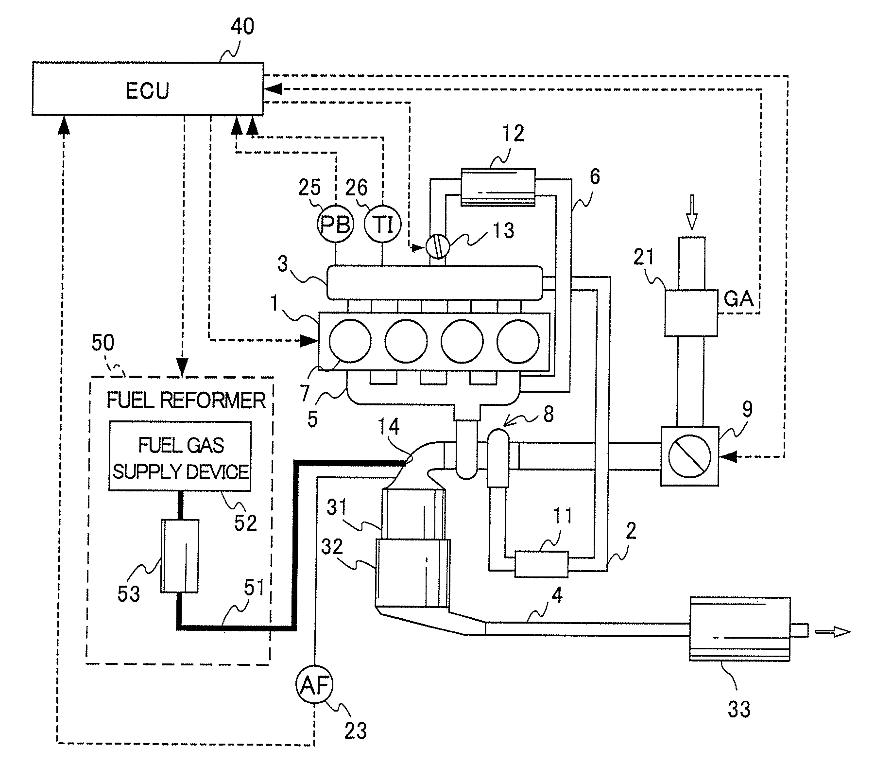
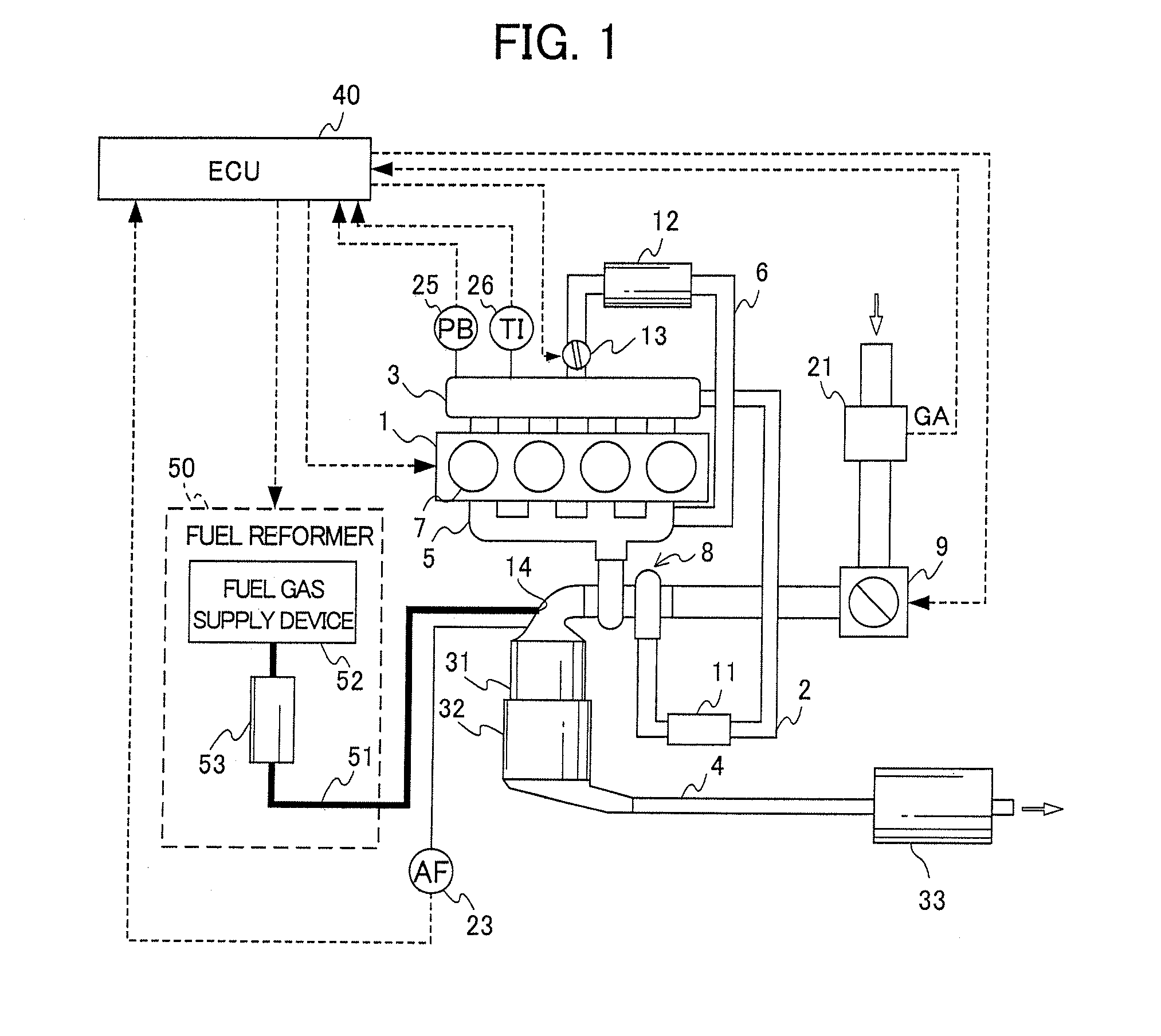
[0132]FIG. 1 is a view showing a configuration of an internal combustion engine and an exhaust purification device thereof according to the first embodiment of the present invention. An internal combustion engine (hereinafter referred to as “engine”) 1 is a diesel engine that directly injects fuel into the combustion chamber of each cylinder 7, and fuel injectors, which are not illustrated, are provided to each of the cylinders 7. These fuel injectors are electrically connected by an electronic control unit (hereinafter referred to as “ECU”) 40, and the valve-open duration and the valve-close duration of the fuel injectors are controlled by the ECU 40.

[0133]The engine 1 is provided with intake plumbing 2 in which intake air flows, exhaust plumbing 4 in which exhaust gas flows, an exhaust-gas recirculation path 6 that recirculates a portion of the exhaust in the exhaust plumbing 4 to ...

example

[0193]In the model gas of the Example, model gas having the below composition was used as gas simulating the gas to which the reductive gas (containing carbon monoxide, hydrogen, and hydrocarbons) produced by the fuel reformer according to the above-mentioned embodiment to the exhaust has been added.

[0194]

Lean AtmosphereNO:90ppmCO:6000ppmHC (propylene):500ppmC (C3H6)O2:6%CO2:6%H2O:7%N2:balance gasH2:5000ppmSV = 50000 h−1Rich AtmosphereNO:90ppmCO:2.1%  HC (propylene):500ppmC (C3H6)O2:0%CO2:6%H2O:7%N2:balance gasH2:6000ppmSV = 50000 h−1

second embodiment

[0199]A second embodiment of the present invention is explained below while referring to the drawings. In the explanation of the second embodiment below, constitutional requirements identical to the first embodiment are assigned the same reference symbol, and explanations thereof are omitted or simplified.

[0200]FIG. 6 is a view showing a configuration of the engine 1 and the exhaust purification device thereof according to the second embodiment of the present invention. The second embodiment is mainly different from the first embodiment in the configuration of a fuel reformer 50A and the configuration of an ECU 40A.

[0201]In the present embodiment, the fuel reformer 50A is connected into the exhaust plumbing 4 upstream of the NOx purification catalyst 33. In other words, reductive gas produced by the fuel reformer 50A is supplied from an inlet 14A formed in the exhaust plumbing 4 upstream of the NOx purification catalyst 33 into the exhaust plumbing 4.

[0202]An exhaust temperature sen...


PUM

PropertyMeasurementUnit
temperatureaaaaaaaaaa
reduction reaction rateaaaaaaaaaa
pressureaaaaaaaaaa

Abstract

Provided is an exhaust emission control device for an internal combustion engine capable of preventing NOx purification performance from degrading according to the operating condition. The exhaust emission control device comprises a NOx purification catalyst, a catalytic converter for continuously reducing the NOx in the exhaust emissions, a fuel reformer for reforming fuel to manufacture a reformed gas and supplying the reformed gas as the reducing gas from the upstream side of the NOx purification catalyst and the catalytic converter of the exhaust pipe, an operating condition detecting means for detecting the operating condition of an engine, and an enriching means for enriching the exhaust air-fuel ratio. The enriching means enriches the exhaust air-fuel ratio by supplying the reducing gas into the exhaust pipe by using the fuel reformer when the operating condition detected by the operating condition detecting means is a high-load operating condition.

Description

[0001]This application is a National Stage entry of International Application No. PCT / JP2008 / 070926, filed Nov. 18, 2008, which claims priority to Japanese Patent Application No. 2008-001695, filed Jan. 8, 2008; Japanese Patent Application No. 2008-001696, filed Jan. 8, 2008; and Japanese Patent Application No. 2008-001700, filed Jan. 8, 2008, the disclosure of the prior applications are incorporated in their entirety by reference.TECHNICAL FIELD[0002]The present invention relates to an exhaust purification device for an internal combustion engine. More specifically, it relates to an exhaust purification device for an internal combustion engine provided with a NOx purification catalyst that adsorbs or occludes NOx in exhaust, and that reduces the NOx thereby adsorbed or occluded.[0003]In addition, in the present invention, the terminology “rich” indicates a ratio of air / fuel (hereinafter referred to as “air / fuel ratio”) of fuel that is smaller than a stoichiometric air / fuel ratio, a...

Claims


Application Information

Patent Timeline
Patent Type & Authority Patents(United States)
IPC IPC(8): F01N3/36
CPCB01D53/9409F01N13/009F01N3/0814F01N3/0885F01N3/2882F02D41/047F02D41/064F02D41/123B01D53/9445B01D2251/202B01D2251/204B01D2255/1021B01D2255/1025B01D2255/206B01D2255/502B01D2255/90B01D2255/908F01N2240/30F01N2570/14F01N2610/03F02D41/1446F02D2200/0804Y02T10/42Y02T10/22Y02A50/20Y02T10/12Y02T10/40
Inventor WADA, KATSUJIISHIMARU, SHINYAIWAMOTO, JUNKOMATSU, NOBUHIRO
Owner HONDA MOTOR CO LTD
Why Eureka
Try Eureka