Liquid crystal display device
a technology of liquid crystal display and display device, which is applied in the direction of semiconductor devices, instruments, metallic oxides, etc., can solve the problems of image quality degradation, and achieve the effect of stabilizing the operation characteristics of thin film transistors
- Summary
- Abstract
- Description
- Claims
- Application Information
AI Technical Summary
Benefits of technology
Problems solved by technology
Method used
Image
Examples
embodiment 1
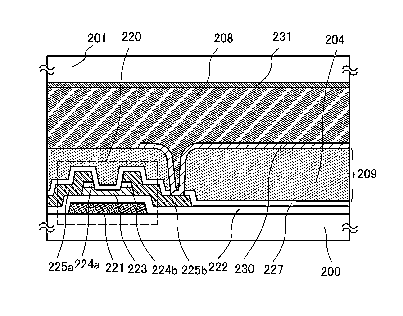
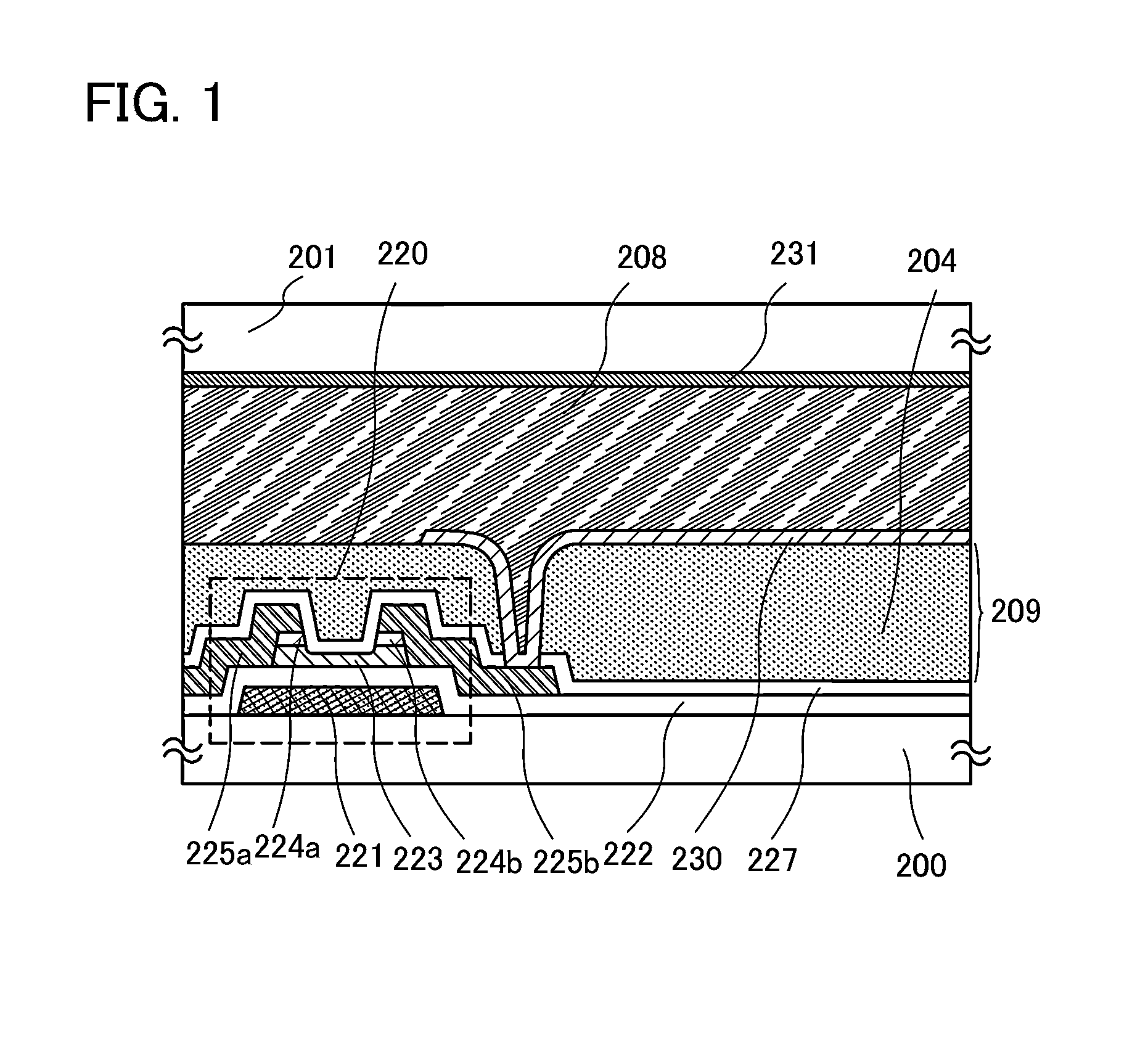
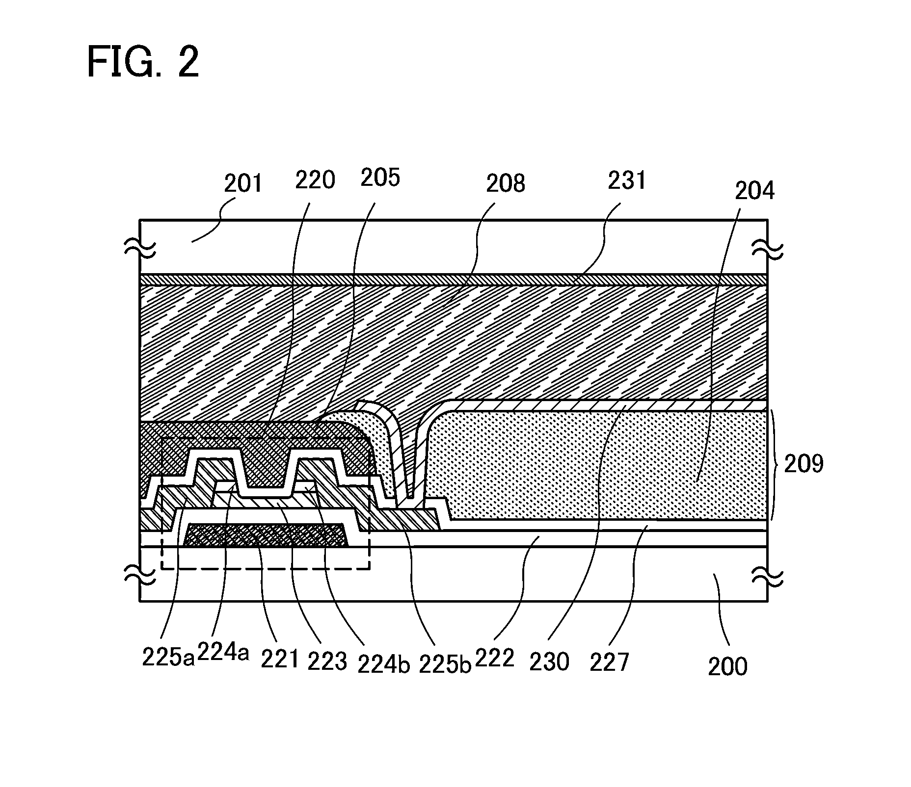
[0047]Liquid crystal display devices and manufacturing methods thereof will be described with reference to FIG. 1, FIG. 2, and FIGS. 17A and 17B.
[0048]FIG. 1, FIG. 2, and FIGS. 17A and 17B are cross-sectional views of liquid crystal display devices.
[0049]In FIG. 1 and FIG. 2, an element layer 203 (see FIGS. 17A and 17B) is formed over a first substrate 200 which is an element substrate, an interlayer film 209 is formed over the element layer 203, and a pixel electrode layer 230 is provided over the interlayer film 209. A liquid crystal layer 208 is sealed between the pixel electrode layer 230 and a counter electrode layer 231 formed on a second substrate 201 which is a counter substrate.
[0050]A mode of a liquid crystal display device illustrated in FIG. 1 includes a plurality of pixels in matrix. In each of the pixels, a thin film transistor including an oxide semiconductor layer, an interlayer film over the thin film transistor, a pixel electrode layer over the interlayer film, and...
embodiment 2
[0079]A liquid crystal display device will be described with reference to FIGS. 18A and 18B.
[0080]FIG. 18A is a plan view of a liquid crystal display device illustrating one pixel. FIG. 18B is a cross-sectional view taken along line X1-X2 in FIG. 18A.
[0081]In FIG. 18A, a plurality of source wiring layers (including a wiring layer 405a) are provided in parallel to each other (extended in a vertical direction in the drawing) and apart from each other. A plurality of gate wiring layers (including a gate electrode layer 401) are provided apart from each other and extend in a direction generally perpendicular to the source wiring layers (a horizontal direction in the drawing). Common wiring layers 408 are provided adjacent to the plurality of gate wiring layers and extend in a direction generally parallel to the gate wiring layers, that is, in a direction generally perpendicular to the source wiring layers (a horizontal direction in the drawing). Roughly rectangular spaces are surrounded...
embodiment 3
[0130]In Embodiment 3, examples in which a pixel electrode layer and a common electrode layer are formed in different planes will be described with reference to FIGS. 3A and 3B, FIGS. 4A and 4B, and FIGS. 7A and 7B. Note that components in common with those in Embodiments 1 and 2 can be formed using a similar material and manufacturing method, and detailed description of the same portions and portions having similar functions is omitted.
[0131]FIG. 3A, FIG. 4A, and FIG. 7A are plan views of liquid crystal display devices, each illustrating one pixel. FIG. 3B, FIG. 4B, and FIG. 7B are cross-sectional views taken along line X1-X2 in FIG. 3A, FIG. 4A, and FIG. 7A, respectively.
[0132]In each of the plan views of FIG. 3A, FIG. 4A, and FIG. 7A, in a manner similar to that of Embodiment 2, a plurality of source wiring layers (including a wiring layer 405a) are provided in parallel to each other (extended in a vertical direction in the drawing) and apart from each other. A plurality of gate ...
PUM
 Abstract
Description
Claims
Application Information
 - R&D
- Intellectual Property
- Life Sciences
- Materials
- Tech Scout
- Unparalleled Data Quality
- Higher Quality Content
- 60% Fewer Hallucinations
Browse by: Latest US Patents, China's latest patents, Technical Efficacy Thesaurus, Application Domain, Technology Topic, Popular Technical Reports.
© 2025 PatSnap. All rights reserved.Legal|Privacy policy|Modern Slavery Act Transparency Statement|Sitemap|About US| Contact US: help@patsnap.com


