Supercharge Your Innovation With Domain-Expert AI Agents!

Electrode bundle

a technology of electrode bundles and bundles, applied in the field of medical electrode bundles, can solve the problems of inability to maintain the original position of the implanted wire electrode, therapy failure, and ineffectiveness, and achieve the effect of not causing excessive tissue damag

Active Publication Date: 2013-06-04
NEURONANO AB
View PDF24 Cites 0 Cited by
  • Summary
  • Abstract
  • Description
  • Claims
  • Application Information

AI Technical Summary

Benefits of technology

This patent describes an electrode that can be placed in soft tissue without causing excessive damage and easily retained in place over an extended period of time. It can be manufactured easily and allows for the insertion of ultra thin electrodes into deep tissue while reducing the risk of dislocation due to tissue movements. The electrode bundle includes a barb element surface that can anchor it into tissue, and the electrodes are coated with a biocompatible material to improve their insertion and anchoring properties, as well as reduce scar formation.

Problems solved by technology

A particular problem with known electrodes of this kind is their retention at the desired site in tissue, in particular in the brain, over an extended period of time, such as from one week to one month and event for one year or more.
Dislocation after insertion may make them entirely useless.
For instance, implanted wire electrodes used in pain control are not equipped with anchoring means capable of retaining them in their original position close to the target cells.
Consequently, they are often dislocated after insertion into brain areas that exhibit constant rhythmic movements due to breathing and heart activity, like the brain stem or the spinal cord resulting in therapy failure.
Another problem with known electrodes is damage of brain or other soft tissue caused during insertion.
Known multi-channel electrode arrays with stiff electrodes are vulnerable to tissue acceleration, for example when the patient's head is suddenly moving.
The resulting shearing forces may irritate the tissue or even kill cells adjacent to the electrode.
In addition, there has not been provided a solution to the problem of precisely positioning multiple ultra thin and flexible electrodes deep into the central nervous system.

Method used


Image

  • Electrode bundle
  • Electrode bundle
  • Electrode bundle

Examples


example 1

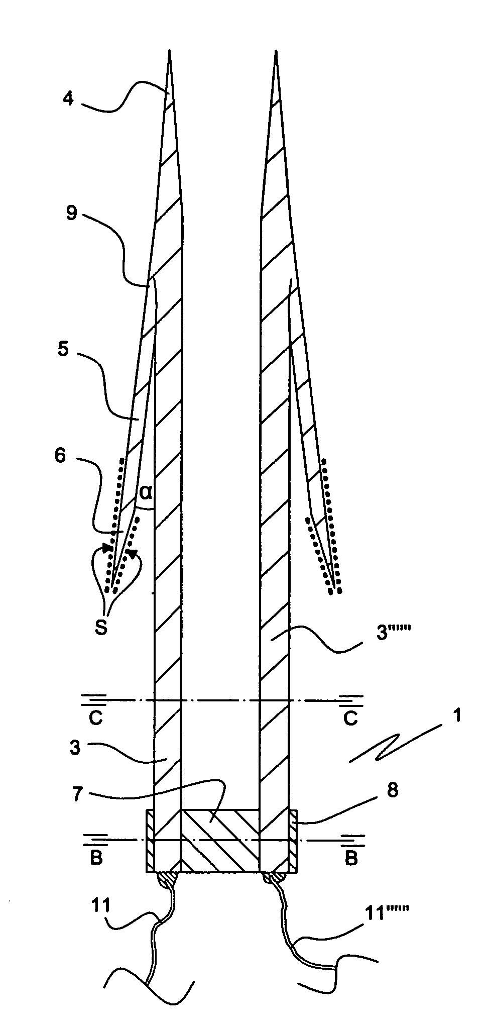
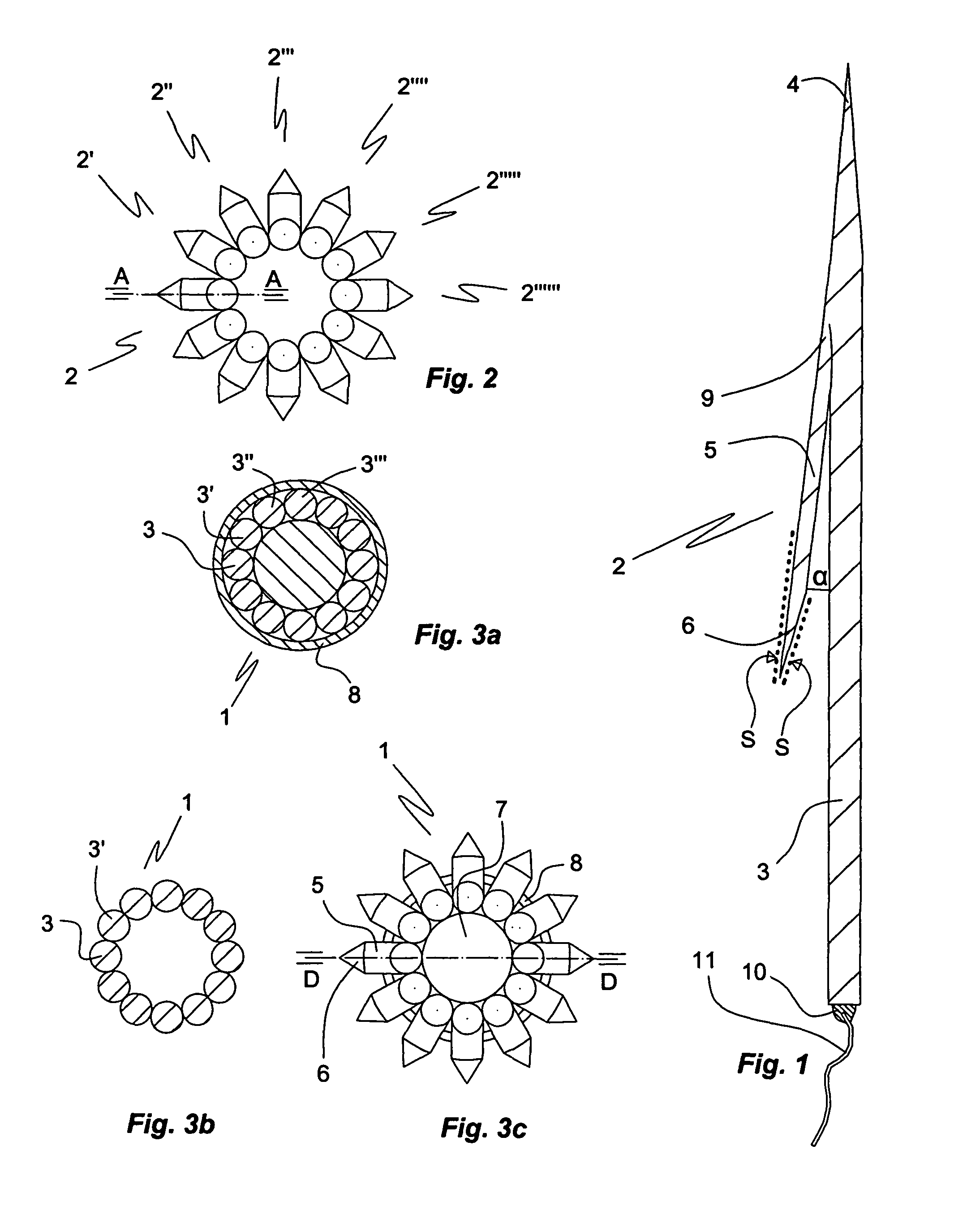
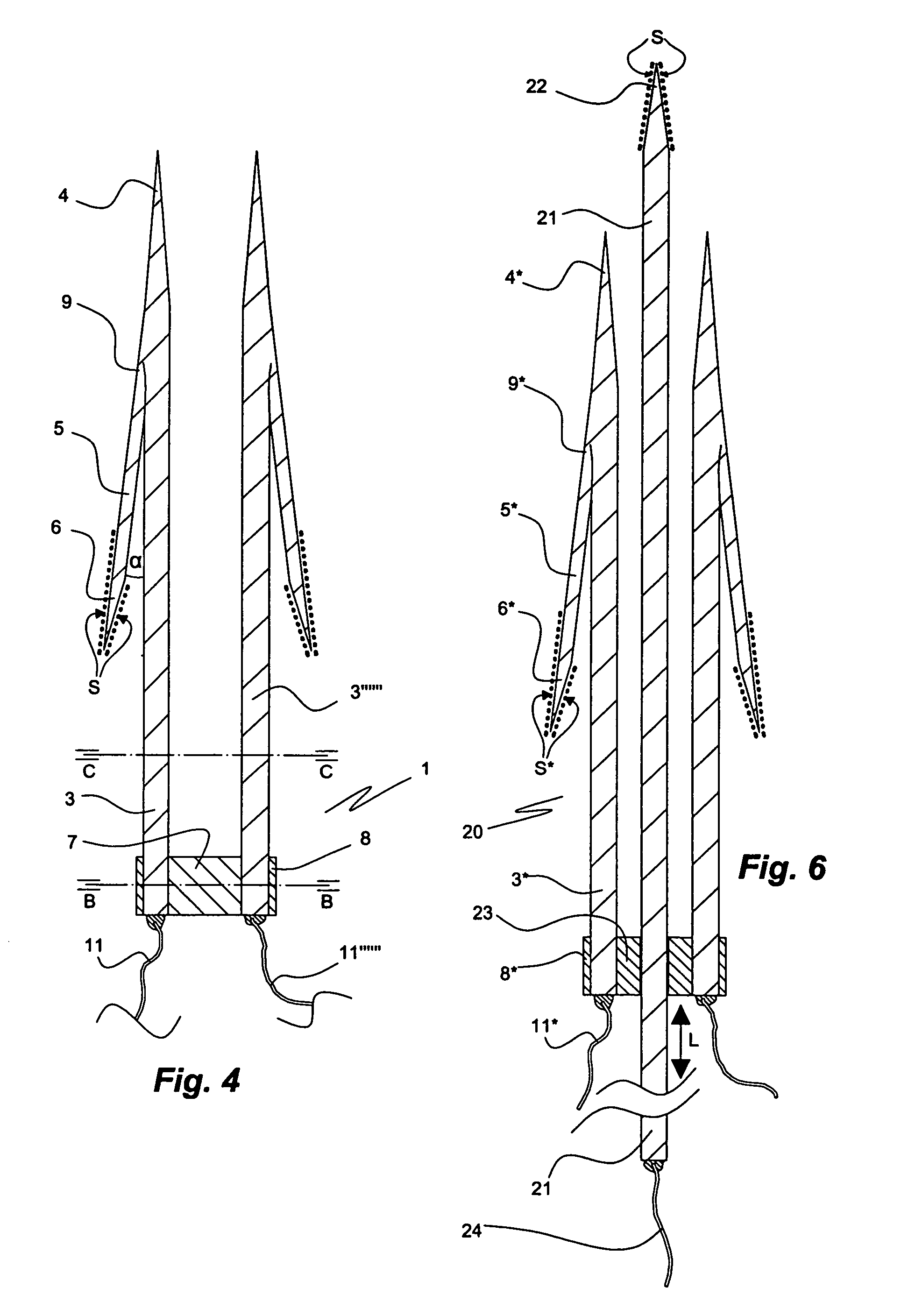
[0041]Preferred embodiments of the electrode bundle of the invention. FIGS. 1 to 5 illustrate a first embodiment of the electrode bundle of the invention in form of an umbrella electrode 1. The umbrella electrode 1 comprises twelve like electrodes 2, 2′, 2″, 2′″, 2″″, 2′″″, 2″″″, etc. An electrode 2 comprises a cylindrical electrically conducting electrode rod 3 having a tip 4 at its one (front) end. An integral anchoring element or barb 5 having a tip 6 at its free end extends in a skew rearward fashion from a section of the electrode rod 3 near the tip 4 in the direction of the blunt distal end of the electrode rod 3, to which a thin insulated wire 11 is attached by a solder 10. The electrode rod 3 and the barb 5 are made of a good conductor such as platinum, silver, gold, copper, their alloys and other suitable metals and alloys; carbon fibres and fibres of electrically conducting polymers may also be used. The electrode element 3 and the barb 5 can also be made of a core of non-...

example 2

[0054]Positioning the Electrode Bundle in Tissue.

[0055]For optimal performance of the electrode it is critical to place it with high precision in the target tissue, in particular neuronal tissue. Since the size of the brain and spinal cord and the relative size and location of their various regions varies considerably between individuals, coordinate guided insertion is not sufficiently accurate. Preferably a ‘tracking’ procedure is used to locate the coordinates of the brain or spine region of interest. In this procedure the correct coordinates are determined by multiple recording / stimulation traces with single electrodes. They may also be determined by tracking by means of a guiding electrode like the guiding electrode 21 of the embodiment of FIGS. 6 and 7. Once the correct coordinates are determined they can be used to guide the insertion of the electrode bundle into the brain. The electrode bundle can be introduced into tissue by means of a micromanipulator capable of temporarily...

example 3

[0057]Electrical Control of / Recording of Electrical Signals by the Electrode Bundle.

[0058]For an electrode of the invention intended for signal recording purposes, the electrode elements are electrically connected to a signal amplifying unit comprising an amplifying circuit and, optionally, a transmitter for wireless connection to a control unit. To avoid loss of signal strength the amplifying unit with the transmitter is disposed close to the electrode bundle. For transmission over a short distance, such as up to about 20 cm, a miniaturized first transmitter may be mounted at the rear portion of the bundle, that is, at a portion extending from the spinal cord or brain tissue, transmitting the signals to a transfer unit comprising a receiver and a second transmitter. The transfer unit may be implanted in soft tissue and comprise a wirelessly rechargeable battery.

[0059]An electrode of the invention intended for stimulation is connected to a preferably telemetrically controlled stimul...


PUM


Abstract

An electrode bundle for implantation in soft tissue comprises two or more electrodes aligned in parallel. Each electrode comprises an electrode element, an anchoring element joined to the electrode element at a portion intermediate between the front end and the rear end thereof and a means bundling the electrodes disposed between the anchoring element and the rear end. The anchoring element forms an angle α from 0° to 6° with the electrode element and extends in the direction of the rear end thereof. Also disclosed is a stack of electrode bundles, methods for insertion of the bundle and the stack into soft tissue, and their uses.

Description

FIELD OF THE INVENTION[0001]The invention relates to a medical electrode bundle for insertion into soft tissue such as the brain, the spinal cord, endocrine organs, muscles, and connective tissue.BACKGROUND OF THE INVENTION[0002]Electrodes that can be implanted for a long time into the central nervous system (CNS) have a wide application. In principle, all brain nuclei can be recorded from or stimulated by such electrodes and their functions monitored and controlled. Stimulation of the brain or spinal cord can be of particular value in situations when brain nuclei are degenerated or injured. Monitoring brain activity can be useful if linked to drug delivery or other measures such as electrical stimulation. Electrodes can also be used to lesion specific sites in tissue. To record and stimulate brain structures various forms of implanted electrodes have been developed and used in the past. For a long time implantable electrodes have been used for symptomatic treatment of Parkinson's d...

Claims


Application Information

Patent Timeline
Patent Type & Authority Patents(United States)
IPC IPC(8): A61N1/05A61B5/0531A61B5/291A61B5/296
CPCA61B5/0478A61N1/0531A61N1/0539A61N1/0551A61N1/0529A61B5/0492A61B2562/125A61N1/05A61N1/0558A61B5/4064A61B5/407A61B5/4076A61B5/291A61B5/296A61B5/293
Inventor SCHOUENBORG, JENS OLAF ROE
Owner NEURONANO AB
Features
  • R&D
  • Intellectual Property
  • Life Sciences
  • Materials
  • Tech Scout
  • Unparalleled Data Quality
  • Higher Quality Content
  • 60% Fewer Hallucinations
Learn More