

Method and system for acoustically treating material
a technology of acoustic energy and acoustic treatment, which is applied in the direction of enzymology, instruments, transportation and packaging, etc., can solve the problems of limiting reaction applications to non-critical processes, distorted acoustic field, and defocused energy distribution, etc., to achieve high throughput and hinder the use of ultrasound
- Summary
- Abstract
- Description
- Claims
- Application Information
AI Technical Summary
Benefits of technology
Problems solved by technology
Method used
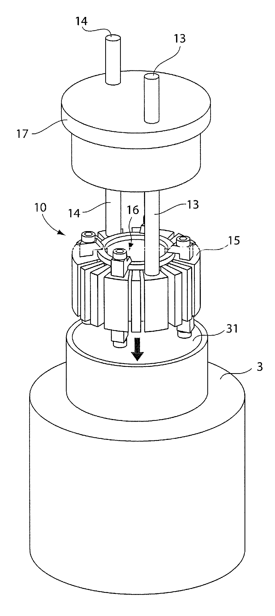
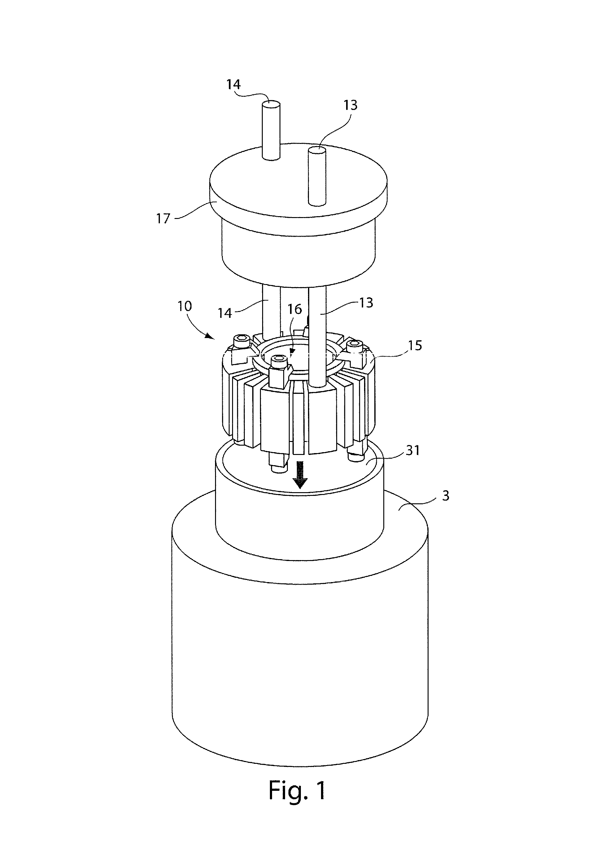
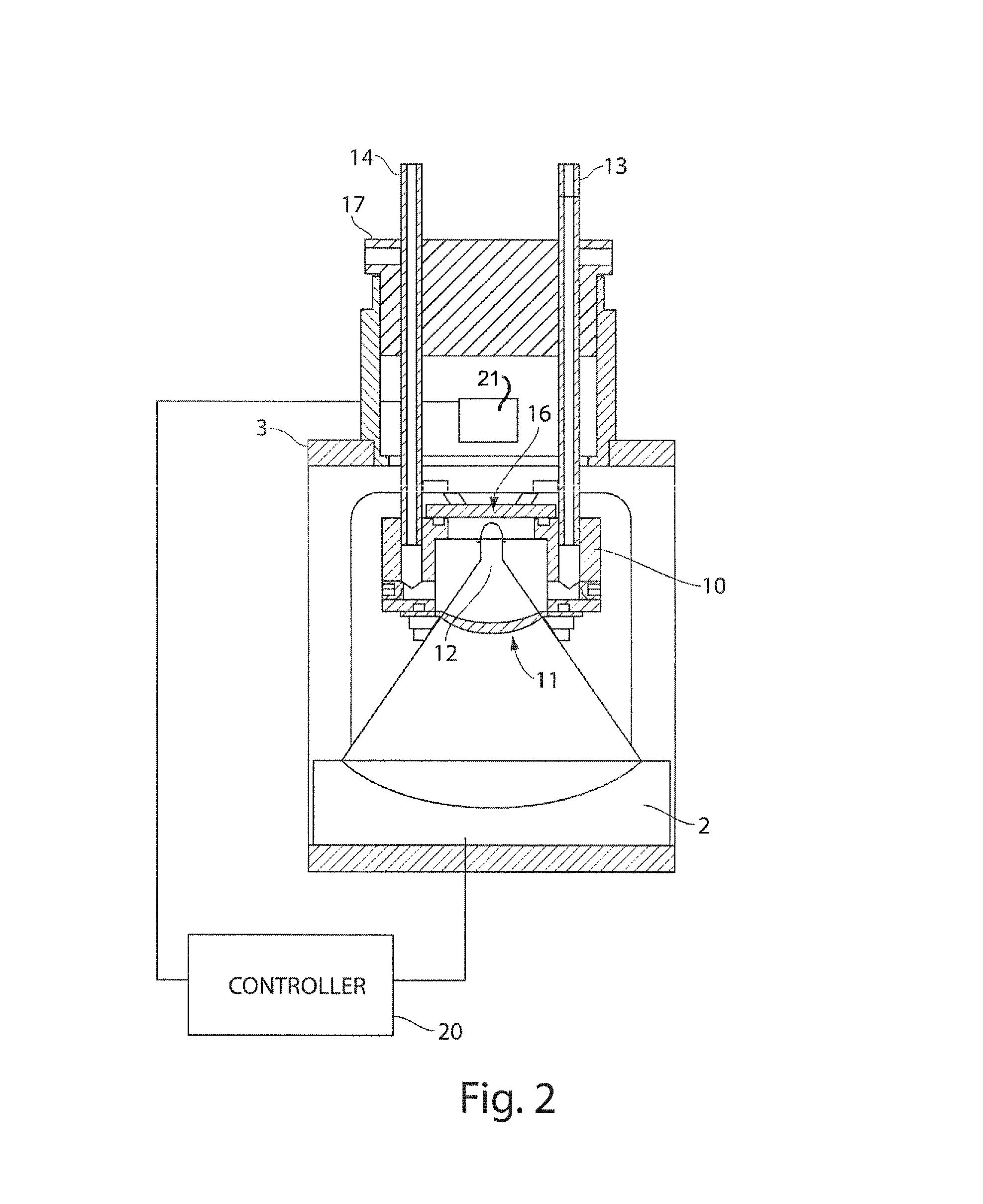
Image

Examples
Embodiment Construction
[0031]“Sonic energy” as used herein is intended to encompass such terms as acoustic energy, acoustic waves, acoustic pulses, ultrasonic energy, ultrasonic waves, ultrasound, shock waves, sound energy, sound waves, sonic pulses, pulses, waves, or any other grammatical form of these terms, as well as any other type of energy that has similar characteristics to sonic energy. “Focal zone” or “focal point” as used herein means an area where sonic energy converges and / or impinges on a target, although that area of convergence is not necessarily a single focused point, but may include a volume of varying size and shape. As used herein, the terms “process chamber” or “processing zone” as used herein means a vessel or region where the sonic energy converges, and the sample material is present for treatment. As used herein, “nonlinear acoustics” can mean lack of proportionality between input and output. For example, as the amplitude applied to the acoustic transducer increases, the sinusoidal...
PUM
| Property | Measurement | Unit |
|---|---|---|
| frequency | aaaaa | aaaaa |
| frequency | aaaaa | aaaaa |
| power | aaaaa | aaaaa |
Abstract
Description
Claims
Application Information