
Silicone composition and organic light-emitting diode

a light-emitting diode and organic technology, applied in the field of composition, can solve the problems of high acidity, high resistance to electrochemical reactions, and many limitations of the hole-transport layer comprising pdot:pss, and achieve the effects of low turn-on voltage, high brightness, and high transparency

Inactive Publication Date: 2013-07-02
DOW CORNING CORP
View PDF25 Cites 1 Cited by
  • Summary
  • Abstract
  • Description
  • Claims
  • Application Information

AI Technical Summary

Benefits of technology

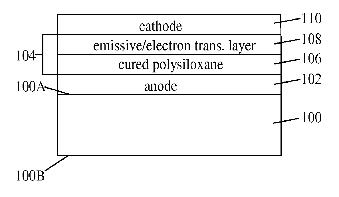
The resulting OLEDs demonstrate low turn-on voltage, high brightness, and improved stability, with the polysiloxane layer providing enhanced performance and durability in OLED devices.

Problems solved by technology

However, a hole-transport layer comprising PDOT:PSS has many limitations including low transparency, high acidity, susceptibility to electrochemical de-doping (migration of dopant from hole-transport layer) and electrochemical decomposition.
Moreover, PDOT:PSS is insoluble in organic solvents and aqueous emulsions of the polymer, used to prepare the hole-transport layer, have limited stability.

Method used


Image

  • Silicone composition and organic light-emitting diode
  • Silicone composition and organic light-emitting diode
  • Silicone composition and organic light-emitting diode

Examples


example 1

[0116]2-Allylthiophene (25 g), 13 g of anhydrous toluene (13 g), and 250 mg of Platinum Catalyst were combined under nitrogen in a three-neck flask equipped with a reflux condenser and a dropping funnel. Then, 30 g of trichlorosilane was added drop-wise to the mixture. Upon completion of the addition, the mixture was heated to 60° C. and maintained at that temperature for 2 h. Then, the mixture was distilled at 150° C. and 0.02 ton to give 2-(3-trichlorosilylpropyl)thiophene as a colorless liquid: 1H NMR (CDCl3) δ 7.16 (dd, 1H, J=5.1, 0.9 Hz); 6.95 (dd, 1H, J=4.8, 3.3 Hz); 6.83 (m, 1H); 2.96 (t, 2H, J=7.2 Hz); 1.98 (m, 2H); 1.46 (m, 2H).

[0117]2-(3-Trichlorosilylpropyl)thiophene (5.0 g) and 50 g of methyl isobutyl ketone were combined in a flask. Then, 400 mg of silicon tetrachloride and 430 mg of 1,8-bis(trichlorosilyl)octane were added to the solution. The resulting mixture was cooled at −78° C. for 1 h. Next, 10 g of water was added to the mixture during a period of 1 h. When the ...

example 2

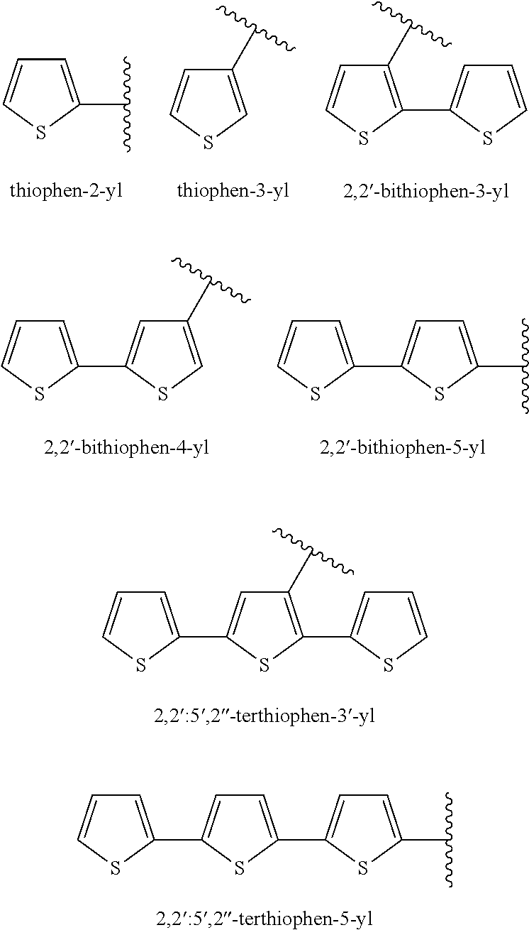
[0118]The hydrosilylation reaction of Example 1 was repeated using 18.7 g of 5-allyl-2,2′-bithiophene in place of 2-allylthiophene, 10 g of anhydrous toluene, 20 g of trichlorosilane, and 150 mg of Platinum Catalyst. 5-(3-Trichlorosilylpropyl)-2,2′-bithiophene was obtained as a colorless liquid: 1H NMR (CDCl3) δ 7.20 (dd, 1H, J=5.1, 1.2 Hz); 7.14 (dd, 1H, J=3.6, 0.9 Hz); 7.02 (m, 2H); 6.74 (d, 1H, J=3.6 Hz); 2.93 (t, 2H, J=7.2 Hz); 1.99 (m, 2H); 1.49 (m, 2H).

[0119]The hydrolysis reaction of Example 1 was repeated using 5-(3-trichlorosilylpropyl)-2,2′-bithiophene in place of 2-(3-trichlorosilylpropyl)thiophene.

example 3

[0120]The hydrosilylation reaction of Example 1 was repeated using 4.5 g of 2-allyl-5-methylthiophene in place of 2-allylthiophene, 2.5 g of anhydrous toluene, 5.0 g of trichlorosilane, and 50 mg of Platinum Catalyst. 2-(3-Trichlorosilylpropyl)-5-methylthiophene was obtained as a colorless liquid: 1H NMR (CDCl3) δ 6.60 (m, 2H); 2.88 (t, 2H, J=7.2 Hz); 2.47 (s, 3H); 1.95 (m, 2H); 1.47 (m, 2H).

[0121]The hydrolysis reaction of Example 1 was repeated using 2-(3-trichlorosilylpropyl)-5-methylthiophene in place of 2-(3-trichlorosilylpropyl)thiophene.


PUM

PropertyMeasurementUnit
temperatureaaaaaaaaaa

Abstract

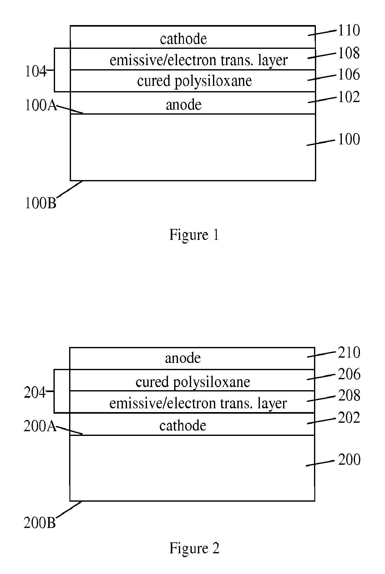
A silicone composition comprising (A) a hydrolysis product prepared by reacting at least one thiophenyl-substituted silane and a cross-linking agent with water in the presence of an organic solvent to form an organic phase containing the hydrolysis product and an aqueous phase, and separating the organic phase from the aqueous phase, and (B) an organic solvent; and an organic light-emitting diode (OLED) containing a hole-transport / hole-injection layer comprising a cured polysiloxane prepared by applying the aforementioned silicone composition to form a film and curing the film.

Description

CROSS REFERENCE TO RELATED APPLICATIONS[0001]This application is a U.S. national stage filing under 35 U.S.C. §371 of PCT Application No. PCT / US09 / 034848 filed on 23 Feb. 2009, currently pending, which claims the benefit of U.S. Provisional Patent Application No. 61 / 039,455 filed 26 Mar. 2008 under 35 U.S.C. §119 (e). PCT Application No. PCT / US09 / 034848 and U.S. Provisional Patent Application No. 61 / 039,455 are hereby incorporated by reference.FIELD OF THE INVENTION[0002]The present invention relates to a silicone composition and more particularly to a silicone composition comprising (A) a hydrolysis product prepared by reacting at least one thiophenyl-substituted silane and a cross-linking agent with water in the presence of an organic solvent to form an organic phase containing the hydrolysis product and an aqueous phase, and separating the organic phase from the aqueous phase; and (B) an organic solvent. The present invention also relates to an organic light-emitting diode (OLED)...

Claims


Application Information

Patent Timeline
Patent Type & Authority Patents(United States)
IPC IPC(8): H01L51/50H10K99/00
CPCC08G77/28C08L83/08H01L51/0094H01L51/5088H01L51/5048H10K85/40H10K50/14H10K50/17H10K50/171
Inventor SUZUKI, TOSHIOWITKER, DAVID
Owner DOW CORNING CORP
Learn More