
Electron gun for a multiple beam klystron with magnetic compression of the electron beams

Active Publication Date: 2013-10-01
CALABAZAS CREEK RES
View PDF16 Cites 11 Cited by
  • Summary
  • Abstract
  • Description
  • Claims
  • Application Information

AI Technical Summary

Benefits of technology

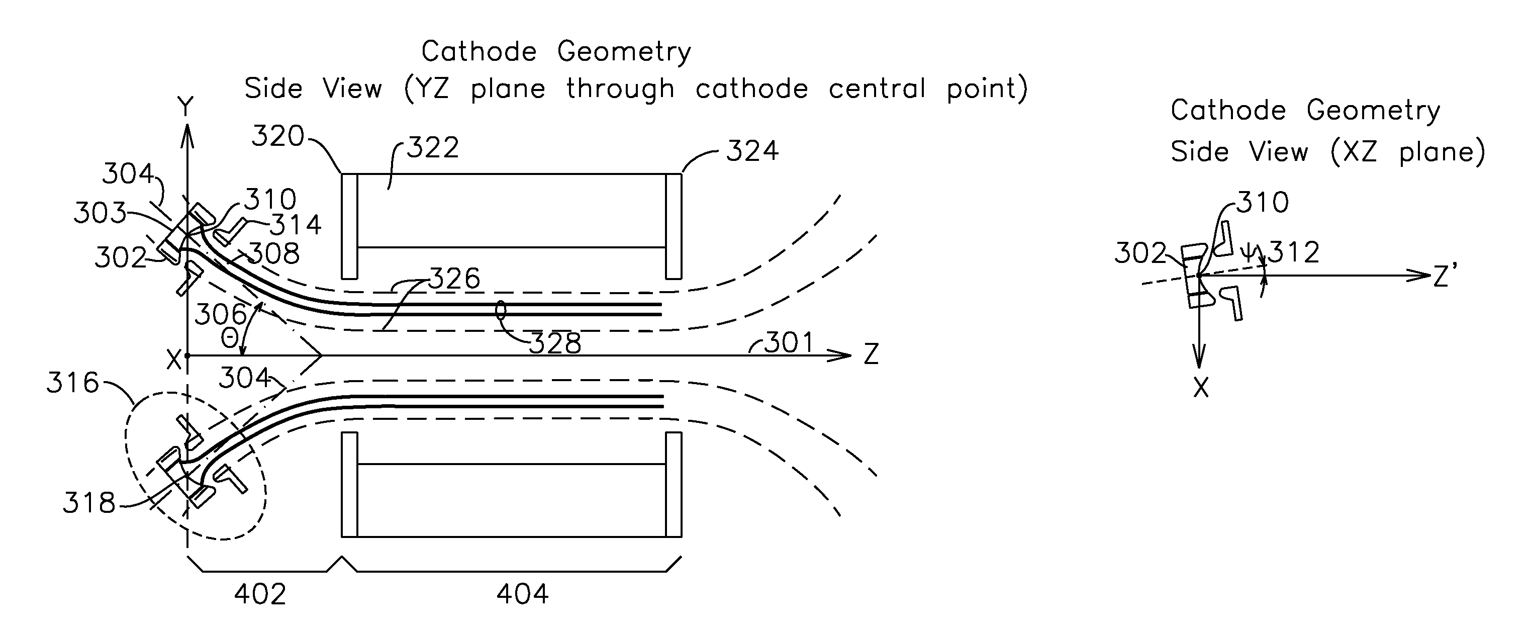
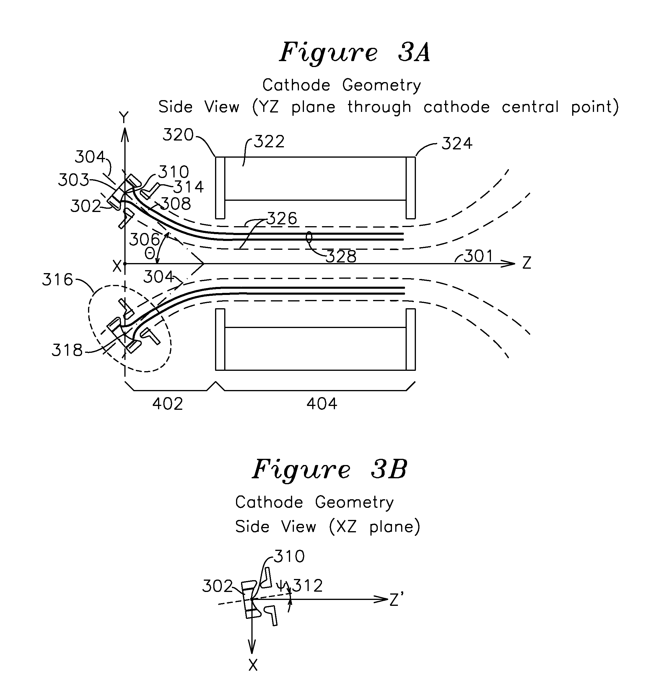
The present invention relates to an electron gun assembly for generating parallel electron beams. The technical effect of the invention is to cancel out the spiraling motion of electron beams in the RF circuit, which reduces the available energy in the beam and causes energy to be lost through beam spreading and break-up, by eliminating the necessity of a spiraling beam tunnel through the RF circuit. To achieve this, the invention uses a magnetic field with a uniform flux region and a diverging flux region to compress the electrons of different electron gun assemblies around their local axis and along the device axis, resulting in parallel electron beams over the uniform flux region of the Z axis.

Problems solved by technology

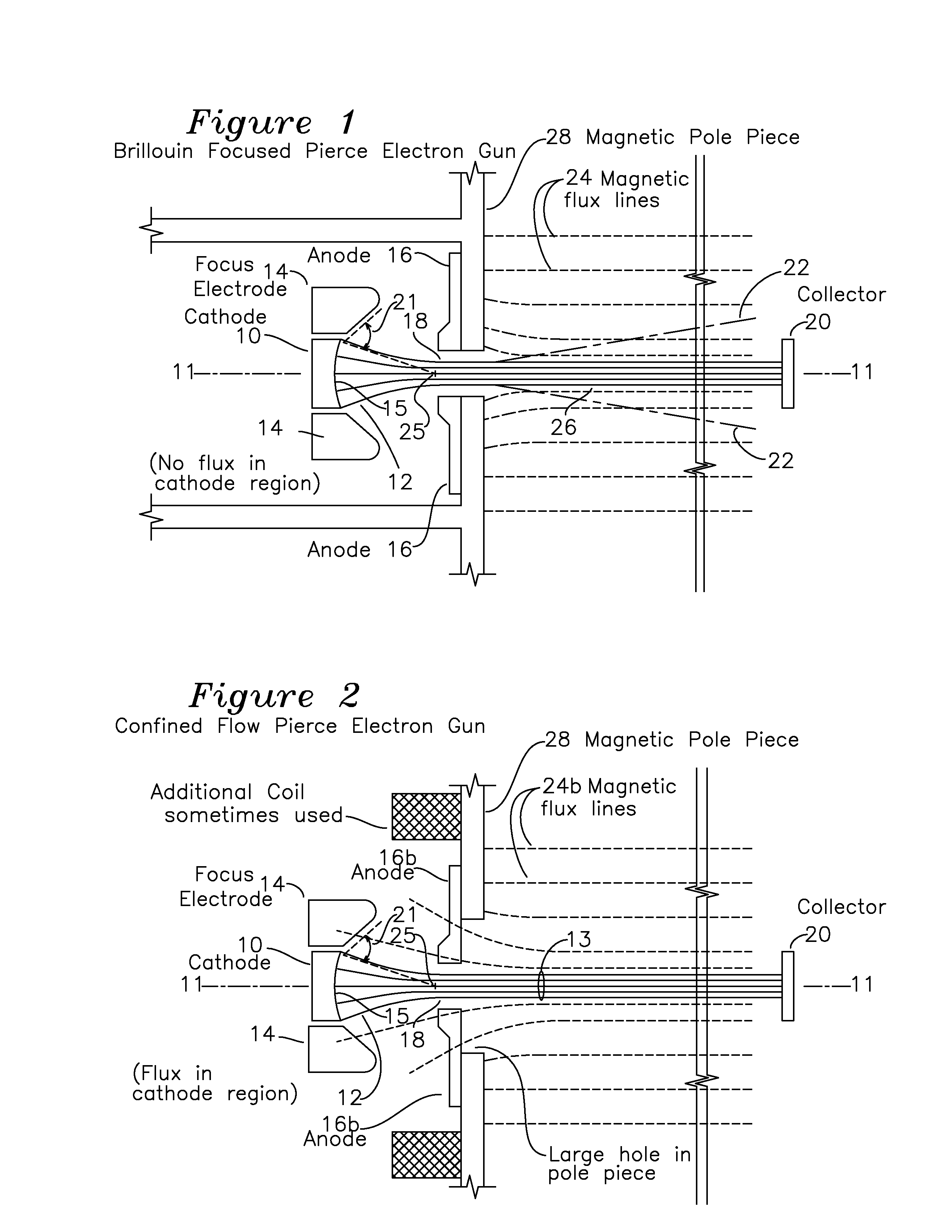
The device described by Symons does not provide for confined flow focusing, as it can be seen that no magnetic focusing field is applied, and beam focusing is performed entirely by electrostatic potentials applied to the many grids.
Consequently, the beam will not be fully confined in the presence of space charge bunching, limiting the average and peak power capability of the device.
Consequently, the number of beams that can propagate through a fundamental mode cavity becomes limited by mechanical and thermal constraints.
The disadvantage of this structure is that the large physical area creates additional capacitance, which implies a narrow band of operation compared to a device having physically smaller RF structures.
Additionally, the enlarged resonant cavities of Bohlen can also support oscillation of parasitic modes that can disrupt proper operation of the device.
In the prior art, this is done because no alternative electron beam design has been discovered.
None of the prior art devices teaches compression of the multiple beams toward the device axis and resulting in parallel beams in the RF circuit axial extent of the device, such that the distance from the central axis to the electron beam in the RF cavity axial extent is significantly less than the distance from the cathode center to the device central axis at the electron gun.

Method used


Image

  • Electron gun for a multiple beam klystron with magnetic compression of the electron beams
  • Electron gun for a multiple beam klystron with magnetic compression of the electron beams
  • Electron gun for a multiple beam klystron with magnetic compression of the electron beams

Examples


Embodiment Construction

[0035]Prior art multiple beam klystrons have been developed where the electron beams emitted from multiple cathodes propagate parallel to the device axis at the same radius from the device central axis as the cathodes. There are two types of multiple beam guns currently available for these devices: non-convergent and convergent.

[0036]In the non-convergent devices, electron beam focusing is provided by immersing the electron gun and drift tubes in a uniform magnetic field which guides the electrons along the magnetic flux lines to the drift tubes. In a non-convergent electron gun, the diameter of the emitting surface is the same as the electron beam that propagates through the RF device. The non-convergent electron beams of this class of device have limited current density, which prevent them from developing more power at higher frequencies. The amount of current that can be emitted from the cathode is dependent on the size of the emitting surface and the maximum electron emission de...


PUM


Abstract

A multi-beam electron gun provides a plurality N of cathode assemblies comprising a cathode, anode, and focus electrode, each cathode assembly having a local cathode axis and also a central cathode point defined by the intersection of the local cathode axis with the emitting surface of the cathode. Each cathode is arranged with its central point positioned in a plane orthogonal to a device central axis, with each cathode central point an equal distance from the device axis and with an included angle of 360 / N between each cathode central point. The local axis of each cathode has a cathode divergence angle with respect to the central axis which is set such that the diverging magnetic field from a solenoidal coil is less than 5 degrees with respect to the projection of the local cathode axis onto a cathode reference plane formed by the device axis and the central cathode point, and the local axis of each cathode is also set such that the angle formed between the cathode reference plane and the local cathode axis results in minimum spiraling in the path of the electron beams in a homogenous magnetic field region of the solenoidal field generator.

Description

[0001]The present invention was developed under the United States Department of Energy grant DE-FG02-06ER86267. The government has certain rights in this invention.FIELD OF THE INVENTION[0002]The present invention relates to linear beam electron devices, and more particularly, to an electron gun that provides multiple convergent electron beamlets suitable for use in a multiple beam klystron using confined flow magnetic focusing.BACKGROUND OF THE INVENTION[0003]Linear beam electron devices are used in sophisticated communication and radar systems that require amplification of a radio frequency (RF) or microwave electromagnetic signal. A conventional klystron is an example of a linear beam electron device used as a microwave amplifier. In a klystron, an electron beam is formed by an electron gun which has a thermionic cathode with a negative pulsed or direct current (DC) voltage which thermionically emits electrons that are attracted to a grounded anode through a focusing electrode wh...

Claims


Application Information

Patent Timeline
IPC IPC(8): H01J29/02
CPCH01J25/10H01J23/06H01J3/027
Inventor IVES, R. LAWRENCETRAN, HIEN T.BUI, THUCATTARIAN, ADAMTALLIS, WILLIAMDAVID, JOHNFORSTALL, VIRGINIAANDUJAR, CYNTHIABLACH, NOAH T.BROWN, DAVID B.GADSON, SEAN E.KILEY, ERIN M.READ, MICHAEL
Owner CALABAZAS CREEK RES
Learn More