Method for silica encapsulation of magnetic particles

a magnetic particle and silica technology, applied in the field of magnetic particle encapsulation silica encapsulation, can solve the problems of poor nanoparticle dispersion in solvents, inability to ensure the successful industrial application of nanoparticles, and inherent aggregation of nanoparticles

Active Publication Date: 2013-10-15
IBM CORP
View PDF15 Cites 9 Cited by
  • Summary
  • Abstract
  • Description
  • Claims
  • Application Information

AI Technical Summary

Benefits of technology

[0017]In another embodiment of the present invention, there is provided a method comprising: (a) treating ferrimagnetic and / or ferromagnetic nanoparticles with poly(acrylic acid) (PAA) to form PAA-modified magnetic nanoparticles; and (b) reacting the PAA-modified magnetic nanoparticles with tetramethylorthosilicate (TEOS) to form silica-coated magnetic nanoparticles. The silica encapsulation of the PAA-modified magnetic nanoparticles serves to completely inhibit any magnetically-induced aggregation inherent in the ferrimagnetic and / or ferromagnetic nanoparticles and / or of the PAA-modified magnetic nanoparticles.

Problems solved by technology

A significant challenge to utilizing magnetic nanoparticles for materials applications is the inherent aggregation of nanoparticles that takes place as a result of magnetic interparticle attractions.
Strong magnetic nanoparticle interactions result in poor nanoparticle dispersion in solvents.
The successful synthesis of magnetic nanoparticles by the oleic acid surfactant method, however, does not ensure the successful industrial application of the nanoparticles.
A disadvantage of oleic acid surfactant magnetic nanoparticle synthesis is the instability of the resulting magnetic nanoparticles; specifically, as a result of strong magnetic forces, magnetic nanoparticles in solution have the tendency to irreversibly aggregate and ultimately precipitate from the solution.
This aggregation of the magnetic nanoparticles renders the nanoparticles unsuitable for silica encapsulation.
While this method is suitable for nanoparticles, such as metal nanoparticles, quantum dots, and superparamagnetic particles, this method is not suitable for creating uniform silica shells around magnetic nanoparticles.
In this vein, magnetic nanoparticles are unsuitable for the TEOS method because the strong interparticle magnetic attractions of the magnetic nanoparticles cause irreversible aggregation of the nanoparticles, thus preventing the formation of a uniform silica shell around the individual nanoparticles.
As noted above, the inherent aggregation of magnetic nanoparticles and the formation of non-uniform silica shells around individual and / or clusters of the nanoparticles hinder the production of monodisperse magnetic nanoparticle samples for magnetic applications.

Method used


Image

  • Method for silica encapsulation of magnetic particles
  • Method for silica encapsulation of magnetic particles
  • Method for silica encapsulation of magnetic particles

Examples


example 1

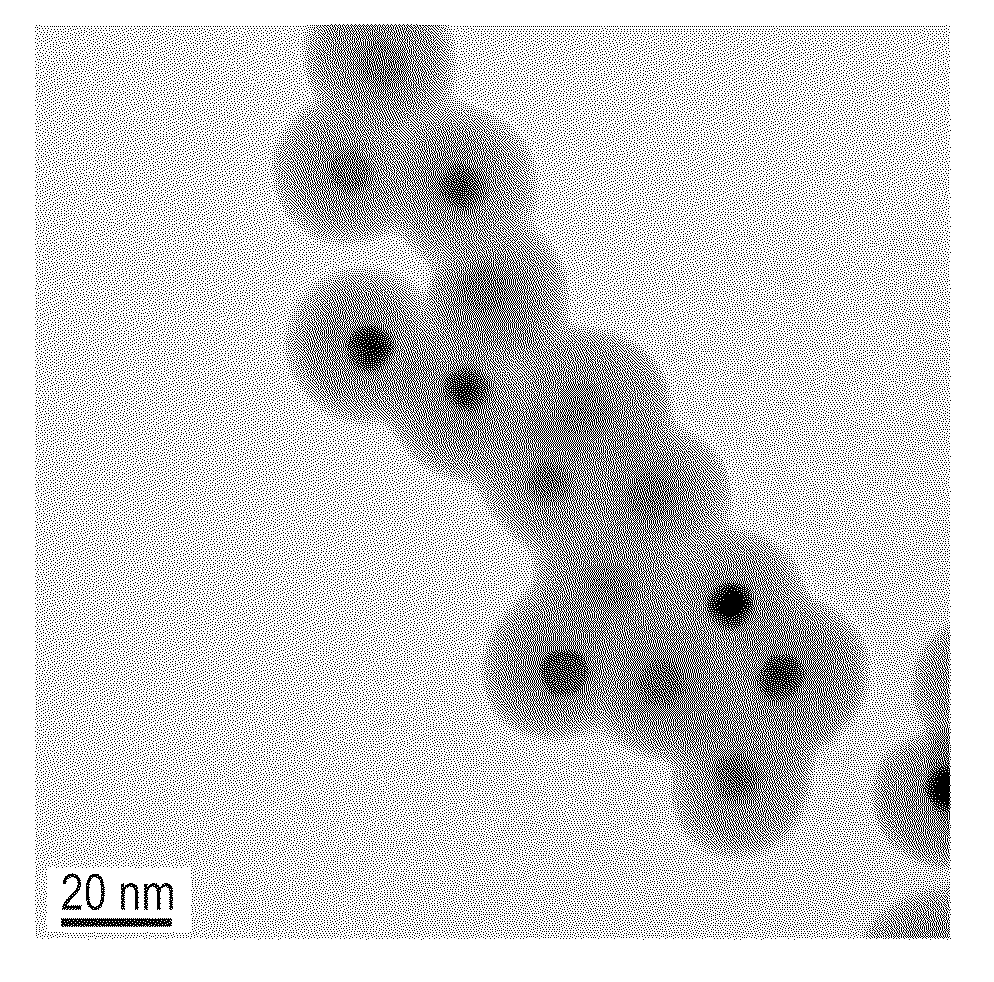
Synthesis of Ferrimagnetic CoFe2O4 Nanoparticles

[0049]Ferrimagnetic CoFe2O4 nanoparticles were synthesized using a modified thermal decomposition method. 2 mmol Fe(acac)3, 1 mmol Co(acac)2, 10 mmol 1,2-hexadecanediol, 6 mmol oleic acid, 6 mmol oleylamine, and 20 mL of benzyl ether were combined and mechanically stirred under a flow of N2. The mixture was heated to 200° C. for 2 h and then, under a blanket of N2, heated to reflux (˜300° C.) for 1 h. The resulting black colored mixture was cooled to ambient temperature. Next, 40 mL of ethanol was added to the mixture and the resulting black material was precipitated and separated via centrifugation at 6000 rpm for 10 min. The black precipitate was dissolved in hexane with 0.1% oleic acid, and the mixture was centrifuged at 6000 rpm for 10 min to remove any undispersed residue. The product was then precipitated with ethanol, centrifuged to remove the solvent, and dried in vacuum overnight. The average diameter of the CoFe2O4 nanopartic...

example 2

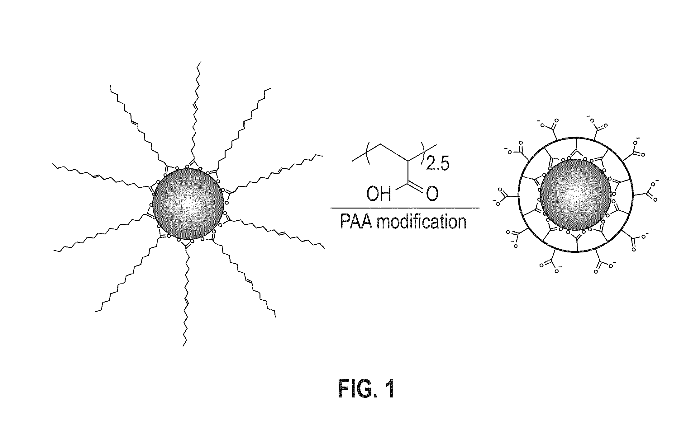
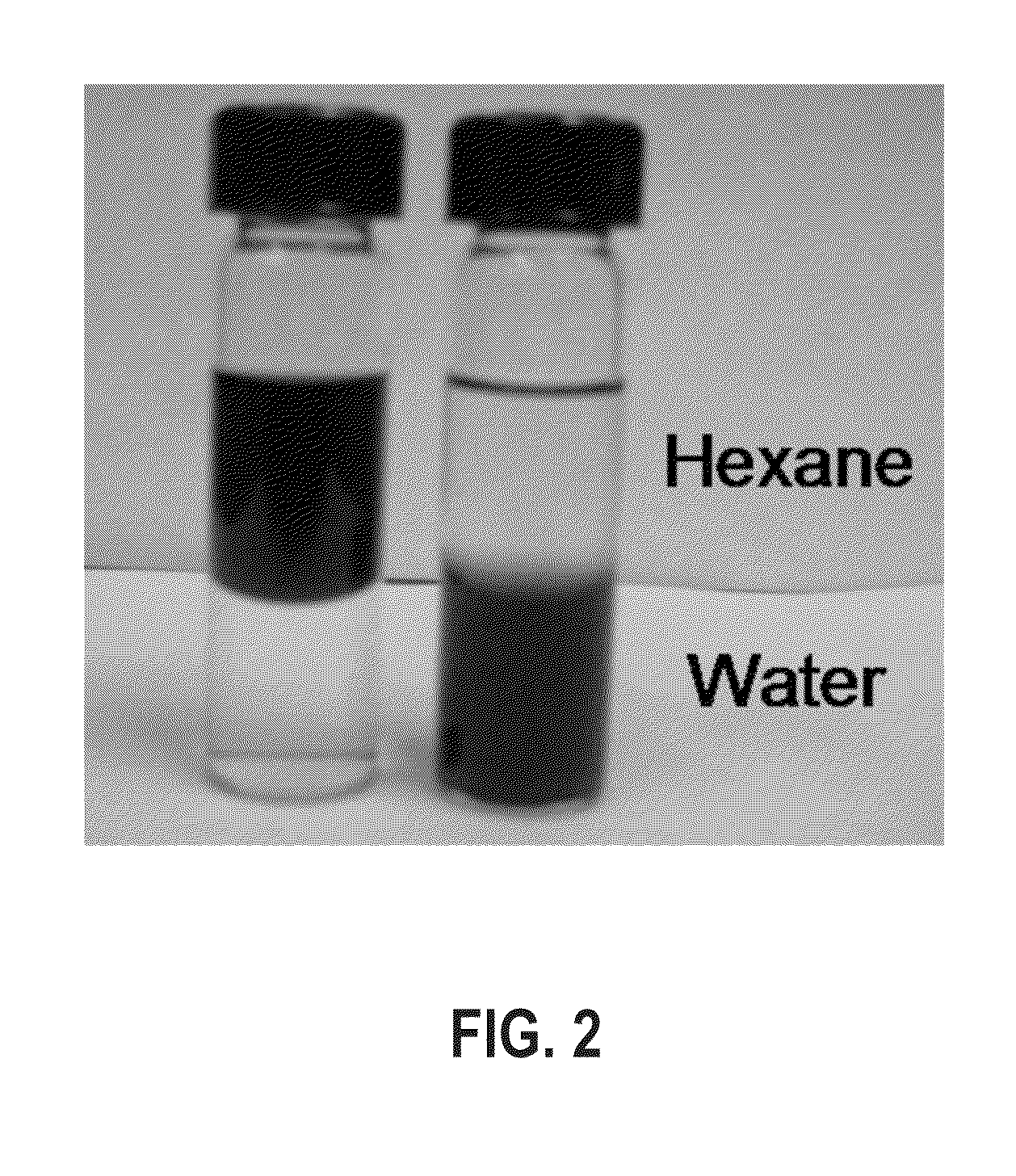
PAA Surface Modification of 18 nm CoFe2O4 Nanoparticles

[0052]In a glass container under ambient conditions, 1 mL of PAA in tetrahydrofuran (THF) solution (10 mg / mL) was added to a dispersion of the synthesized 18 nm CoFe2O4 nanoparticles (10 mg in 10 mL) from Example 1. The mixture was shaken for 2 hours with occasional sonication. The modified particles were separated with a magnet and the solvent was decanted. The particles were washed three times with hexane and methanol to remove any free oleic acid and excess PAA polymers. The washed particles were dispersed in aqueous solution by ionizing the carboxylic groups with a dilute NaOH solution.

[0053]FT-IR spectroscopy was utilized to characterize the functional groups present on the particle surface after the PAA ligand exchange. FIG. 6 shows a comparative FT-IR graph of the unmodified and PAA-modified CoFe2O4 nanoparticles. As shown in FIG. 6, the unmodified CoFe2O4 nanoparticles showed strong CH2 bands at 2923 cm−1 and 2852 cm−1 a...

example 3

Silica Coating of PAA-Modified CoFe2O4

[0056]A 1.5 mL aqueous solution of the PAA-modified CoFe2O4 nanoparticles from Example 2 was diluted with 10 mL of ethanol and 400 μL ammonium hydroxide (30 wt %) with vigorous mechanical stirring. A 200 μL TEOS ethanol solution (10 mM) was added to the mixture every 2 h until the total amount of TEOS solution reached 1 mL. After obtaining the desired size, the silica-coated CoFe2O4 nanoparticles were collected by magnetic separation, washed with ethanol three times, and dispersed in ethanol for further characterization.


PUM

PropertyMeasurementUnit
diameteraaaaaaaaaa
thicknessaaaaaaaaaa
shell thicknessaaaaaaaaaa

Abstract

Provided is a method of inhibiting magnetically induced aggregation of ferrimagnetic and / or ferromagnetic nanoparticles by encapsulating the nanoparticles in a silica shell. The method entails coating magnetic nanoparticle surfaces with a polyacid polymer to form polymer-coated magnetic nanoparticles and treating the polymer-coated magnetic nanoparticles with a silica precursor to form uniform silica-coated magnetic nanoparticles. By controlling the thickness of the silica encapsulating the nanoparticles, the inherent magnetically induced aggregation of the nanoparticles can be completely inhibited.

Description

TECHNICAL FIELD[0001]The present invention relates generally to methods for silica encapsulation of magnetic particles. More specifically, the present invention relates to methods for creating a uniform silica coating of a controlled thickness around magnetic nanoparticles that inhibits magnetically induced aggregation of the nanoparticles.BACKGROUND OF THE INVENTION[0002]Surface coating of ferrimagnetic and / or ferromagnetic nanoparticles with desired functionality and controlled magnetic properties is critical to the development of magnetic nanomaterials for high density recording media as well as biomedical applications. A significant challenge to utilizing magnetic nanoparticles for materials applications is the inherent aggregation of nanoparticles that takes place as a result of magnetic interparticle attractions. Strong magnetic nanoparticle interactions result in poor nanoparticle dispersion in solvents. Well-dispersed samples of magnetic nanoparticles are desirable for proce...

Claims


Application Information

Patent Timeline
Patent Type & Authority Patents(United States)
IPC IPC(8): B82Y25/00
CPCC23C18/1212C23C18/122C23C18/1233C23C18/1295H01F1/0054H01F1/344
Inventor DAI, QIUNELSON, ALSHAKIM
Owner IBM CORP
Why Eureka
Try Eureka