Cardiac assist device

a technology of assist device and aorta, which is applied in the direction of catheter, diagnostic recording/measuring, therapy, etc., can solve the problems of rare transplant organs, reduced blood supply to vitally important organs, and death of patients, so as to reduce the risk of aortic rupture, facilitate the implantation of fluid supply lines, and reduce the resistance of fluid supply lines

Inactive Publication Date: 2013-11-19
SURGERY IN MOTION
View PDF5 Cites 81 Cited by
  • Summary
  • Abstract
  • Description
  • Claims
  • Application Information

AI Technical Summary

Benefits of technology

[0027]The stent may be self-expandable. Due to the individual variation of the diameter of the aorta, a self-expandable stent may fit better to the patient's aorta, and may help to reduce a risk of a rupture of the aorta.
[0028]In some embodiments, the at least one inflatable element comprises an elastic envelope that comprises an inner circumferential portion enclosing the central opening, an outer circumferential portion attached to the stent and a first and a second cover portion connecting the inner circumferential

Problems solved by technology

Hence, blood supply to vitally important organs may be reduced, which may directly or indirectly lead to death of the patient.
Transplant organs, however, may be rare, and a careful selection of the transplant organ is required in order to avoid a rejection of the transplant organ by the immune system of the patient.
Hence, a considerable amount of time may pass until a transplant organ suitable for the patient can be found, which amount of time may be too long to save the patient's live.
Furthermore, there are many contraindications for heart transplantation such as old age, infections and longstanding high pulmonary pressure.
A problem of cardiac assist devices according to the state of the art is that connecting the cardiac assist device to the circulatory system of the patient may require open heart surgery, which may imply a high risk of complications.
A problem of the intravascular cardiac assist device disclosed in WO 00/35515 is that the incision in the blood vessel,

Method used


Image

  • Cardiac assist device
  • Cardiac assist device
  • Cardiac assist device

Examples


Embodiment Construction

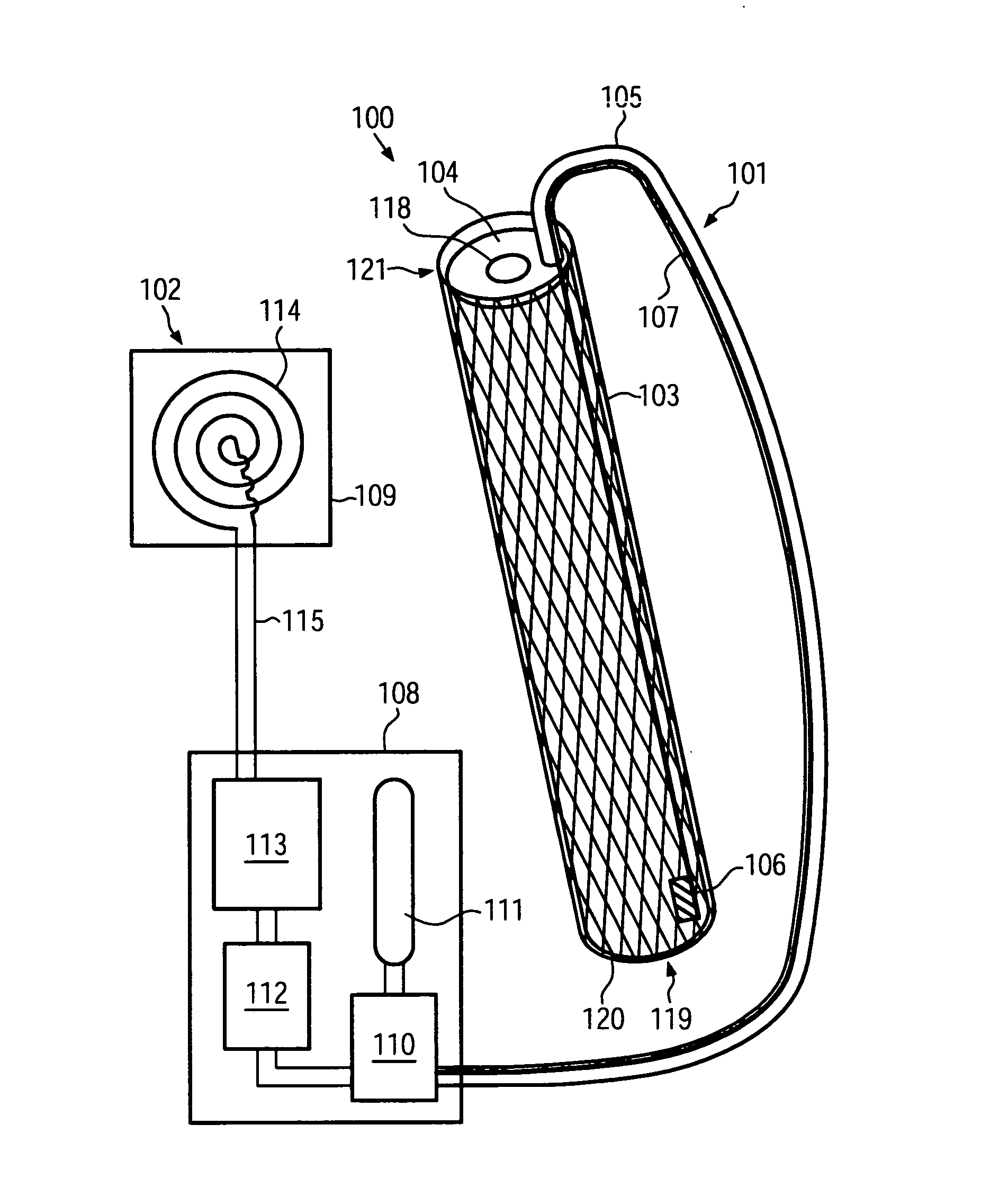
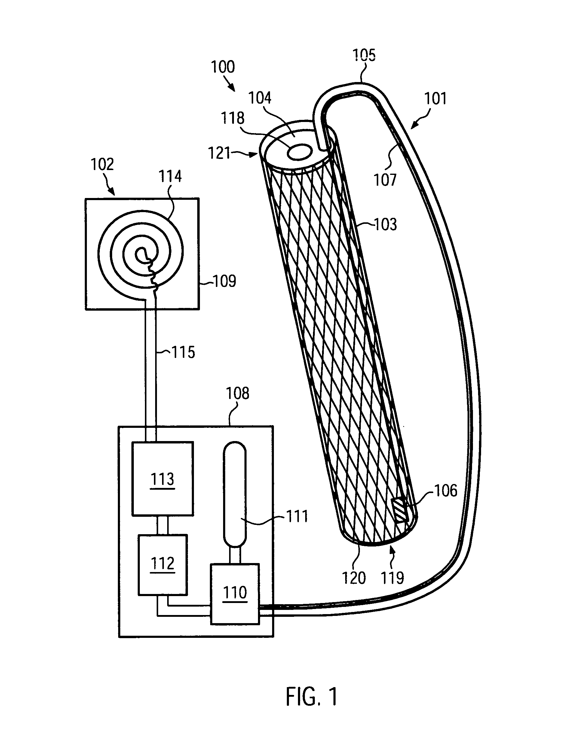
[0042]FIG. 1 shows a schematic cross-sectional view of a cardiac assist device 100 according to an embodiment of the present invention. The cardiac assist device 100 comprises an endovascular portion 101 and an extravascular portion 102. The endovascular portion 101 is configured for implantation into a blood vessel of a patient. The extravascular portion 102 may be configured for implantation into other portions of a patient's body.

[0043]The endovascular portion 101 comprises a stent 103. Similar to stents adapted for the treatment of aortic dissections known to persons skilled in the art, the stent 103 may comprise a wire arranged in a zigzag configuration and / or forming a grating, mesh and / or ring and comprising a metal such as, for example, a stainless steel alloy, a cobalt chrome alloy, titanium, tantalum, platinum or gold. In other embodiments, the stent 103 can comprise a high elastic limit material such as Eligoy. The stent 103 may have a substantially cylindrical shape, enc...


PUM


Abstract

A cardiac assist device (100) comprises a stent 103, 403) which is implantable into a blood vessel of a patient. The stent (103, 403) encloses an inner volume (119, 419). At least one inflatable element (104, 409-413) is attached to the stent (103). The at least one inflatable element (104, 409-413) is provided in the inner volume (119, 419) of the stent (103, 403), wherein the ai least one inflatable element (104, 409-413) annularly encloses a central opening (118, 418) being parallel to a longitudinal axis of said stent (103, 403). The cardiac assist device (100) further comprises a fluid supply adapted for periodically inflating and deflating the at least one inflatable element (104, 409-413), wherein said fluid supply comprises at least one fluid supply line (105, 405) connectable to the at least one inflatable element (104, 409-413) and implantable into a blood vessel of the patient.

Description

FIELD OF THE INVENTION[0001]The present invention generally relates to the filed of cardiac assist devices, in particular to a cardiac assist device which may be implanted at least partially into a blood vessel of a patient to assist the heart of the patient in pumping blood through the circulatory system, to decrease the afterload of the heart, to increase the native ejection fraction and / or to improve the coronary perfusion and the oxygen supply to the myocardium.BACKGROUND OF THE INVENTION[0002]In patients suffering from heart failure which may, for example, be caused by a myocardial infarction, a dilatative or ischemic cardiomyopathy or another disease, the capability of the heart to pump blood through the patient's circulatory system may be reduced to a large extent. Hence, blood supply to vitally important organs may be reduced, which may directly or indirectly lead to death of the patient.[0003]Heart failure may be treated by means of a heart transplantation, wherein the pati...

Claims


Application Information

Patent Timeline
IPC IPC(8): A61N1/362A61M60/135A61M60/268A61M60/427A61M60/515A61M60/538A61M60/857A61M60/871
CPCA61M2205/33A61M2205/3303A61M60/135A61M60/148A61M60/427A61M60/871A61M60/538A61M60/515
Inventor MEHMANESH, HORMOZ
Owner SURGERY IN MOTION
Why Eureka
Try Eureka