Method of preparing positive active material for lithium battery

a lithium battery and active material technology, applied in the field of preparing a positive active material for a lithium secondary battery, can solve the problems of accelerating polarization, reducing the specific surface area of the electrode, and reducing the efficiency of the battery, so as to improve the electrical conductivity, increase the specific surface area of the electrode, and prevent side reactions.

Inactive Publication Date: 2013-11-19
KOREA INST OF SCI & TECH
View PDF19 Cites 0 Cited by
  • Summary
  • Abstract
  • Description
  • Claims
  • Application Information

AI Technical Summary

Benefits of technology

[0013]Therefore, an object of the present invention is to provide a method of preparing a coated positive active material, capable of increasing a specific surface area of an electrode by sophisticatedly preparing an amorphous coating layer on the surface of the positive active material by using a thin film forming process, capable of preventing a side reaction between the positive active material and an electrolyte and enhancing electric conductivity by undergoing a surface coating process, and thus capable of implementing enhanced cycle performance, safety property, and efficiency characteristics for batteries.
[0014]Another object of the present invention is to provide a method of preparing a positive active material capable of enhancing ionic conductivity and capable of preventing a side reaction of a crystalline coating layer and corrosion of metal oxides, by preparing an amorphous mixed metal-oxides coating layer.
[0015]Still another object of the present invention is to provide a battery having stable cycle performance by minimizing melting of a specific component of an active material (Co in case of LiCoO2, Mn in case of LiMn2O4, etc.) and preventing a corrosion reaction at a high voltage, by preventing a secondary reaction between a positive active material and an electrolyte, by coating the surface of the positive active material with an amorphous mixed metal-oxides. Here, the surface of the positive active material is coated with the amorphous mixed metal-oxides since cycle performance of the battery at a high voltage is greatly influenced by the secondary reaction at an interface between the positive active material and the electrolyte.

Problems solved by technology

Firstly, the LiCoO2 is more costly than other positive active materials such as LiNiO2 and LiMn2O4.
Secondly, the LiCoO2 has a low concentration of lithium ions that can be intercalated thereto for maintenance of the structural stability during charge and discharge processes. During the charge process, lithium ions are separated from a lithium layer to form an empty space, and Co4+ ions having similar diameters to each other among Co4+ ions in Co-layers move to the empty space to fill the empty space. The Co4+ ions having moved to the empty space enhance stability of a hexagonal structure, and prevent a phase transition from a monoclinic structure to a hexagonal structure. However, the Co4+ ions hinder movement of the lithium ions, thereby accelerating polarization during the charge and discharge processes. This polarization becomes severe at a high voltage (>4.5V) where the lithium ions are separated from the lithium layer by 50% or more than.
Another problem occurring during the charge and discharge processes at a voltage more than 4.2V may include Co-dissolution due to a side reaction between an electrode and an electrolyte.
As a voltage increases, Co and O are dissolved from each other due to instability of the layered structure.
However, the above methods have the following problems.
Firstly, an initial temperature at which the surface of a positive active material and an electrolyte solution react with each other, i.e., a temperature (Ts) at which oxygen coupled to metal of the positive active material is separated from the metal during a charge process is not sufficiently increased.
Secondly, a heating value occurring during a dissolution process is not sufficiently decreased.
That is, there have not been proposed any techniques capable of enhancing ion conductivity, and capable of preventing a side reaction between an electrolyte and a positive active material, and corrosion of metal oxides by implementing a sophisticated amorphous mixed metal-oxides coating using a thin film processing.

Method used


Image

  • Method of preparing positive active material for lithium battery
  • Method of preparing positive active material for lithium battery
  • Method of preparing positive active material for lithium battery

Examples


example 1

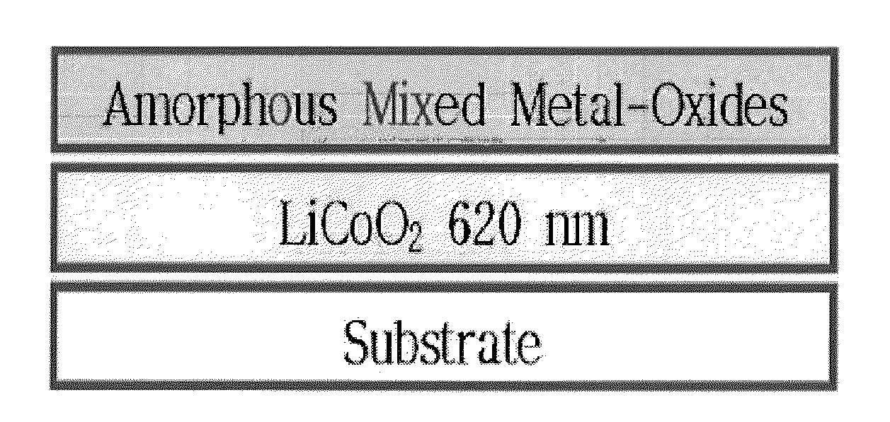
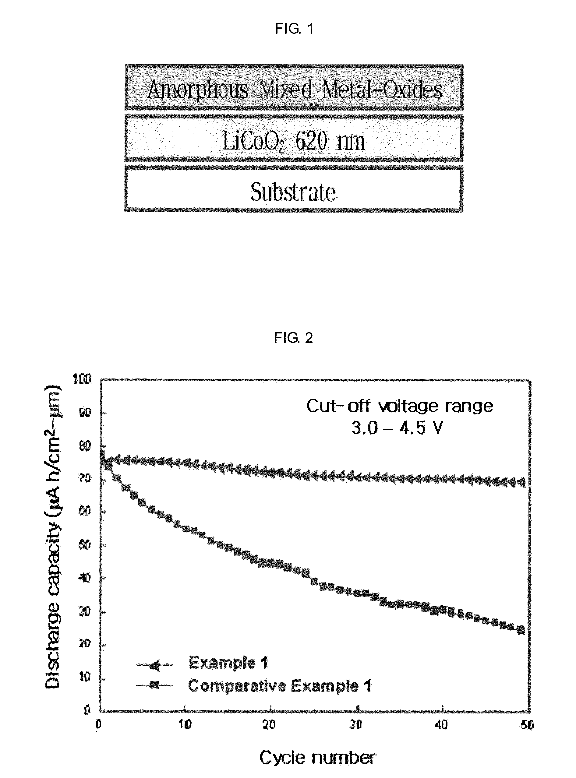
[0051]In this Example 1, was prepared a LiCoO2 thin film positive active material coated with mixed metal-oxides of ZrOx (1.2 at. %)+Al2O3. FIG. 1 is a structural view of an electrode surface-coated with amorphous mixed metal-oxides according to the present invention. From the lower side, the electrode was sequentially deposited with a substrate, LiCoO2 (620 nm), and amorphous mixed metal-oxides (ZrOx(1.2 at. %)+Al2O3, 5-45 nm).

[0052]Hereinafter, will be explained a method of preparing the electrode.

[0053]Firstly, LiCoO2 was deposited on the substrate with a thickness of 620 nm. In order to enhance crystallinity of the deposited positive active material, LiCoO2, a rapid thermal annealing (RTA) process was performed. This RTA process was performed at a high temperature of 650° C. at a pressure of 300 mTorr for five minutes under Ar atmospheres. In order to prevent damages due to drastic temperature changes, temperature increment and temperature decrement were performed by 1° C. per s...

example 2

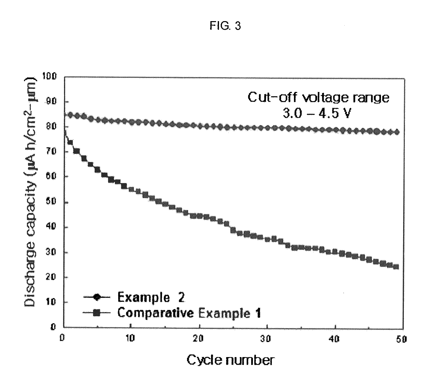
[0057]A thin film positive active material having amorphous mixed metal-oxides (TiOx+Al2O3) as an upper layer according to the present invention has the following structure. From the lower side, the electrode was sequentially deposited with a substrate, LiCoO2 (620 nm), and amorphous mixed metal-oxides (TiOx(1.2 at. %)+Al2O3, 5-45 nm). The multi-layered thin film was deposited and heat-treated by the same procedures as in Example 1, except for the composition of the amorphous mixed metal-oxides (TiOx(1.2 at. %)+Al2O3), a surface coating layer. The surface coating layer used as the upper layer was controlled to have the TiOx composition of 1.2 at. %, by controlling the number of Ti chips on an Al2O3 target having a purity of 99.99%. The deposited LiCoO2 thin film positive active material was used to assemble a half-cell in the same manner as in Example 1, and then cycle performance was experimented. Referring to FIG. 3, when charge and discharge processes were performed 50 times, a L...

example 3

[0058]A thin film positive active material having amorphous mixed metal-oxides (CuOx+Al2O3) as an upper layer according to the present invention has the following structure. From the lower side, the electrode was sequentially deposited with a substrate, LiCoO2 (620 nm), and amorphous mixed metal-oxides (CuOx (1.2 at. %) / +Al2O3, 5-45 nm). The multi-layered thin film was deposited and heat-treated by the same procedures as in Example 1, except for the composition of the amorphous mixed metal-oxides (CuOx (1.2 at. %)+Al2O3), a surface coating layer. The surface coating layer used as the upper layer was controlled to have the CuOx composition of 1.2 at. %, by controlling the number of Cu chips on an Al2O3 target having a purity of 99.99%. The deposited LiCoO2 thin film positive active material was used to assemble a half-cell in the same manner as in Example 1, and then cycle performance was experimented. Referring to FIG. 4, when charge and discharge processes were performed 50 times, ...


PUM

PropertyMeasurementUnit
pressureaaaaaaaaaa
temperatureaaaaaaaaaa

Abstract

Disclosed is a method of preparing a positive active material for a lithium battery. The method comprises: depositing a positive active material on an electrode on a substrate (1); and putting metal chips on a metal oxides target and performing a sputtering process, thereby depositing mixed metal-oxides on the positive active material (2). In another aspect, the method comprises: preparing an electrode active material; preparing a precursor solution including the electrode active material; and printing the precursor solution on the substrate, and evaporating a solvent at a temperature of 80-120° C.

Description

RELATED APPLICATION[0001]The present disclosure relates to subject matter contained in priority Korean Application No. 10-2009-0085059, filed on Sep. 9, 2009, which is herein expressly incorporated by reference in its entirety.BACKGROUND OF THE INVENTION[0002]1. Field of the Invention[0003]The present invention relates to a method of preparing a positive active material for a lithium secondary battery, and particularly, to a method of preparing a positive active material capable of enhancing cell capacity, cycle performance, safety property, and efficiency by preventing a side reaction between a positive active material and an electrolyte, and by enhancing electric conductivity of the positive active material.[0004]2. Background of the Invention[0005]As metal oxides and phosphor oxides positive active materials for lithium secondary batteries, LiCoO2, LiMn2O4, LiMnO2, LiNiO2, LiCO1 / 3Ni1 / 3Mn1 / 3O2, V6O13, V2O5, LiFePO4 or (PO4)3, are being commonly used. As a metal oxides and phosphor...

Claims


Application Information

Patent Timeline
Patent Type & Authority Patents(United States)
IPC IPC(8): C23C14/34
CPCC23C14/083C23C14/3414H01M4/131H01M4/1391H01M4/485H01M4/525H01M4/661H01M10/052Y02E60/122Y02E60/10H01M4/04C23C14/34
Inventor CHUNG, KYUNG YOONCHO, BYUNG WONLEE, SEONG-RAELEE, HWA YOUNGCHOI, JI-AE
Owner KOREA INST OF SCI & TECH
Why Eureka
Try Eureka