Current diverter ring

a current diverter and ring technology, applied in current collectors, supports/enclosements/casings, dynamo-electric machines, etc., can solve the problems of affecting the operation of electrical motors using variable frequency drives. the effect of lubricant leakag

Active Publication Date: 2013-12-10
INPRO INC
View PDF30 Cites 19 Cited by
  • Summary
  • Abstract
  • Description
  • Claims
  • Application Information

AI Technical Summary

Benefits of technology

[0013]An objective of the current diverter ring is to provide an improvement to seals or bearing isolators to prevent leakage of lubricant and entry of contaminants by encompassing the stator within the rotor to create an axially directed interface at the radial extremity of the rotor. It is also an objective of the current diverter ring to disclose and claim an apparatus for rotating equipment that conducts and transmits and directs accumulated bearing current to ground.
[0014]It is another objective of the bearing isolator as disclosed and claimed herein to facilitate placement of a current diverter ring within the stator of the bearing isolator. Conductive segments may be positioned within the current diverter ring. These conductive segments may be constructed of metallic or non-metallic solids, machined or molded. Although any type of material compatible with operating conditions and metallurgy may be selected, bronze, gold, carbon, or aluminum are believed to be preferred materials because of increased conductivity, strength, corrosion and wear resistance.
[0015]It has been found that a bearing isolator having a rotor and stator manufactured from bronze has improved electrical charge dissipation qualities. The preferred bronze metallurgy is that meeting specification 932 (also referred to as 932000 or “bearing bronze”). This bronze is preferred for bearings and bearing isolators because it has excellent load capacity and antifriction qualities. This bearing bronze alloy also has good machining characteristics and resists many chemicals. It is believed that the specified bronze offers increased shaft voltage collection properties comparable to the ubiquitous lightning rod due to the relatively low electrical resistivity (85.9 ohms-cmil / ft @68 F or 14.29 microhm-cm @20 C) and high electrical conductivity (12% IACS @68 F or 0.07 MegaSiemens / cm @20 C) of the material selected.

Problems solved by technology

Adequate maintenance of rotating equipment, particularly electric motors, is difficult to obtain because of extreme equipment duty cycles, the lessening of service factors, design, and the lack of spare rotating equipment in most processing plants.
Lip seals or other contacting shaft seals often quickly wear to a state of failure and are also known to permit excessive amounts of moisture and other contaminants to immigrate into the oil reservoir of the operating equipment even before failure has exposed the interface between the rotor and the stator to the contaminants or lubricants at the radial extremity of the seal.
The problems of bearing failure and damage as applied to electrical motors using variable frequency drives (VFDs) is compounded because of the very nature of the control of electricity connected to VFD controlled motors.
There are many causes of bearing current including voltage pulse overshoot in the VFD, non-symmetry of the motor's magnetic circuit, supply imbalances, and transient conditions, among other causes.
This random and frequent discharging has an electric discharge machining (EDM) effect, which causes pitting of the bearing's rolling elements and raceways.
Eventually, the deterioration will lead to complete bearing failure.3 3See www.Greenheck.com
Most external applications add to costs, complexity, and exposure to external environmental factors.
However, installing insulated bearings does not eliminate the shaft voltage, which will continue to find the lowest impedance path to ground.
Thus, insulated bearings are not effective if the impedance path is through the driven load.
Therefore, the prior art does not teach an internal, low-wearing method or apparatus to efficaciously ground shaft voltage and avoid electric discharge machining of bearings leading to premature bearing failure.

Method used


Image

  • Current diverter ring
  • Current diverter ring
  • Current diverter ring

Examples


first embodiment

of a Single-Piece CDR and Bearing Isolator

[0057]In another embodiment, the CDR 40 and / or bearing isolator 10 may be mounted such that either the CDR 40 and / or bearing isolator 10 are allowed to float in one or more directions. For example, in one embodiment a portion of the bearing isolator 10 is positioned in an enclosure. The enclosure is fashioned as two opposing plates with main apertures therein, through which main apertures the shaft passes 14. The interior of the enclosure is fashioned such that the bearing isolator 10 and / or CDR 40 is positioned within a truncated circle (i.e., pill-shaped) recess on the interior of the enclosure. The contact points between the bearing isolator 10 and / or CDR 40 and the enclosure may be formed with a low friction substance, such as Teflon®, affixed thereto.

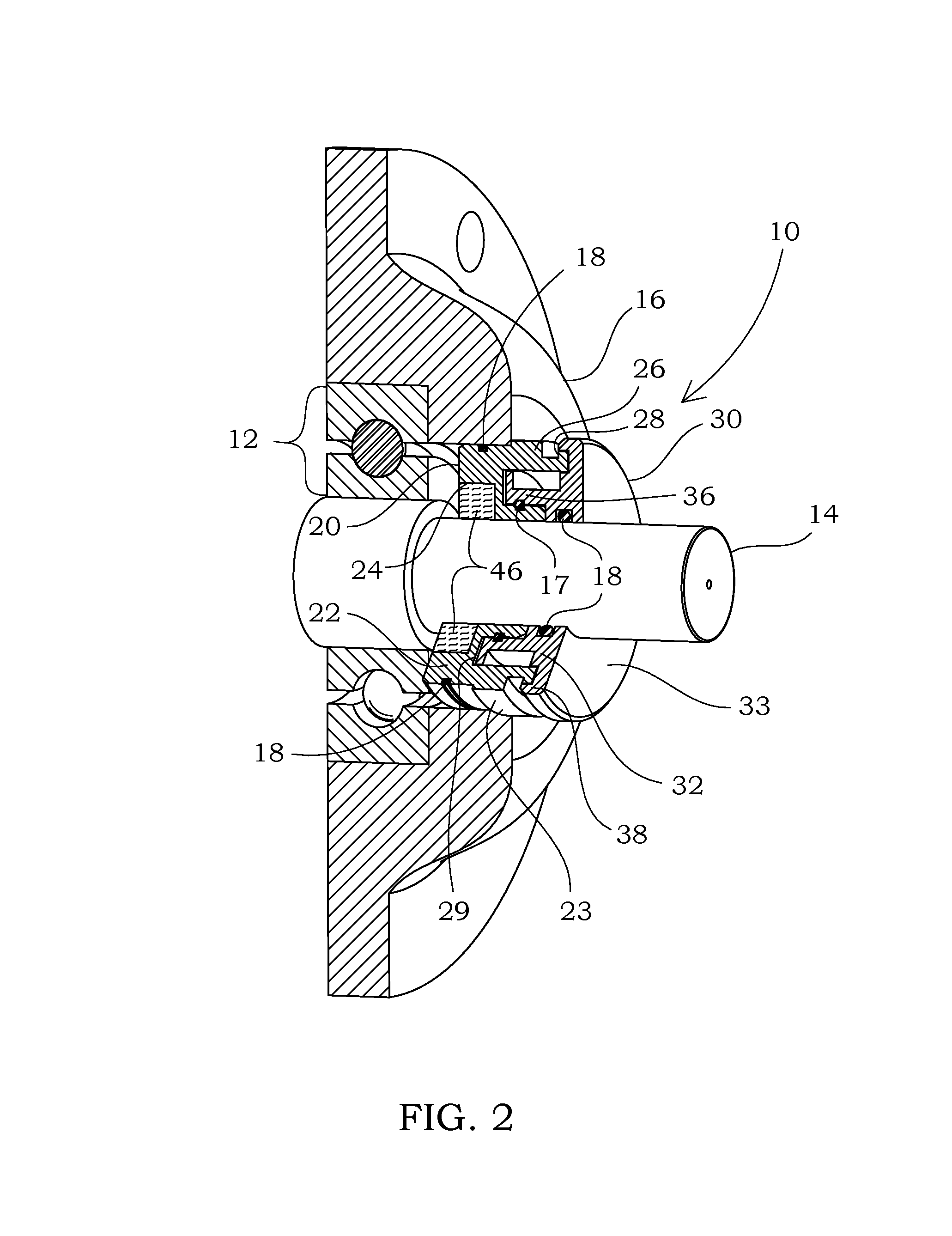
[0058]A more detailed cross-sectional view of one embodiment of a bearing isolator 10 with which the CDR 40 may be used is shown in FIG. 3. The bearing isolator 10 shown in FIGS. 2 and 3 in...

second embodiment

of a Single-Piece CDR

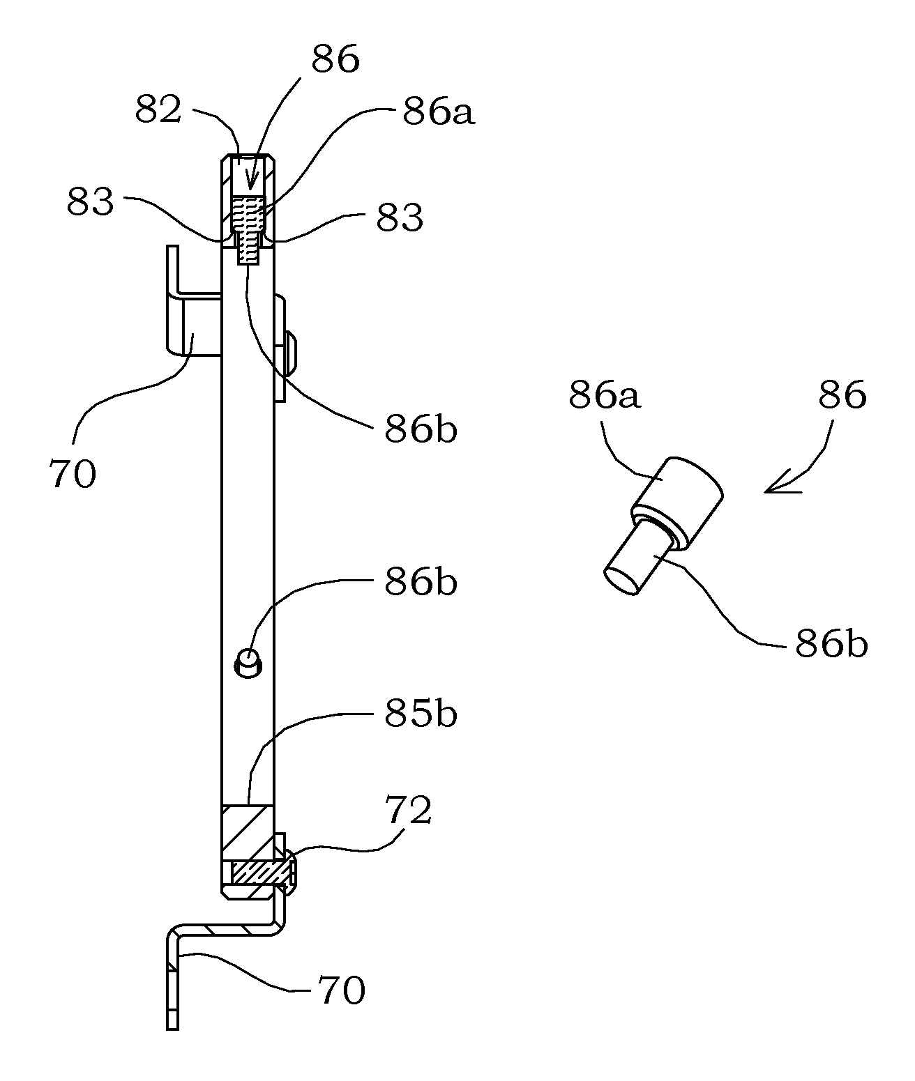
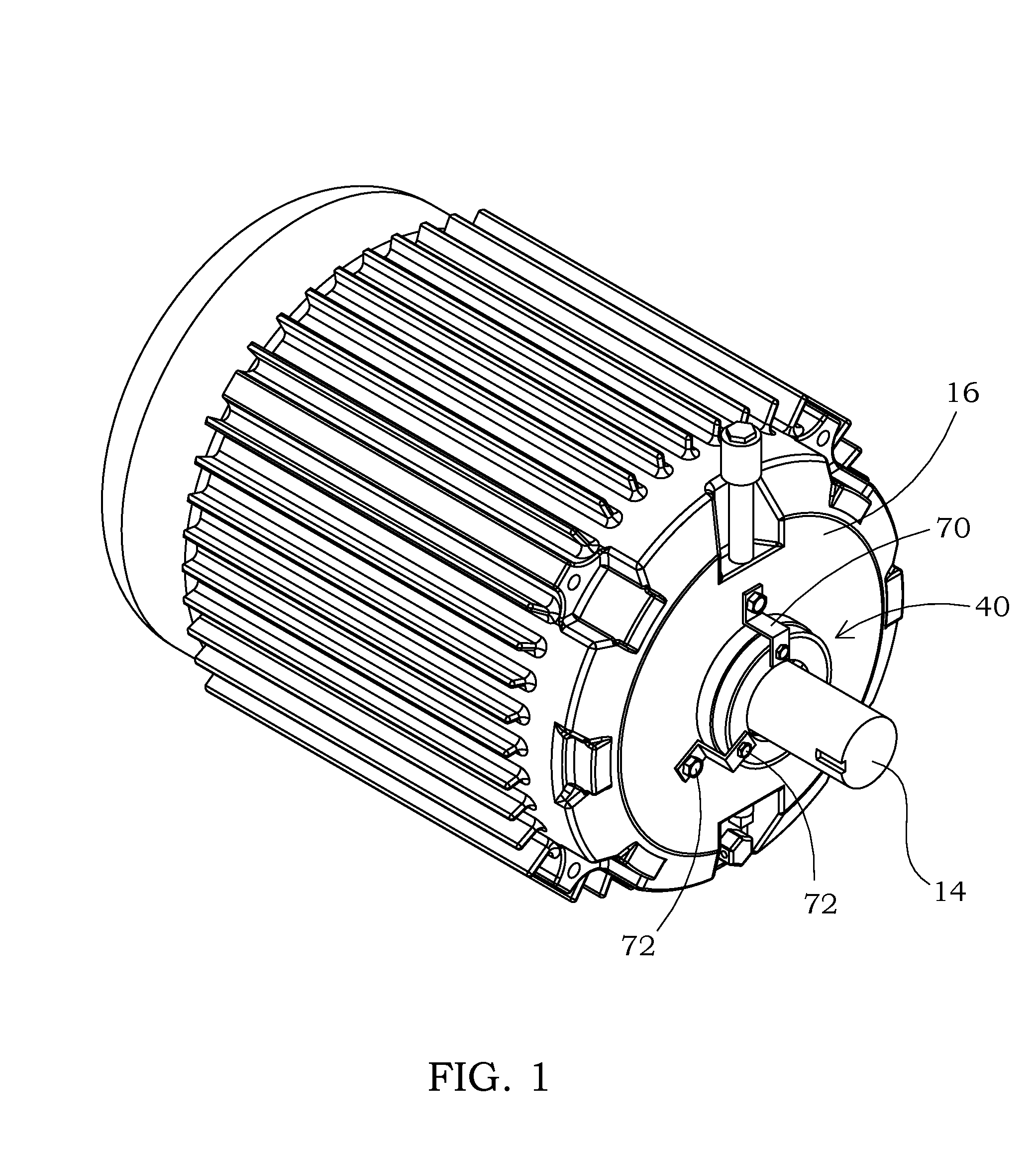
[0091]A radial CDR 80 is another embodiment of a CDR 40, which is shown in FIGS. 15A, 15B as a ring-shaped structure having a main aperture 88 in the center thereof. As with other embodiments of the CDR 40 disclosed herein, the CDR 40 may be mounted to rotational equipment through any structure and / or method without limitation. The embodiment of the radial CDR 80 shown in FIGS. 15A and 15B includes three straps 70 affixed to the radial CDR 80 via fasteners 72. Other fasteners 72 may be used to secure the straps 70 to the rotational equipment, thereby securing the radial CDR 80 to the rotational equipment. In other embodiments of the radial CDR 80, the radial exterior surface 85a of the radial CDR 80 is press-fit into the rotational equipment housing 16. However, the mounting method for the radial CDR is in no way limiting to its scope.

[0092]The embodiment of the radial CDR 80 shown herein includes three radial channels 82 extending from the radial exterior surfa...


PUM


Abstract

The current diverter rings and bearing isolators serve to dissipate an electrical charge from a rotating piece of equipment to ground, such as from a motor shaft to a motor housing. One embodiment of the current diverter ring includes an inner body and an outer body configured to clamp at least one conductive segment between them. In the preferred embodiments of the current diverter ring, the conductive segments are positioned in radial channels. The outer body may be affixed to a shaft, a motor housing, a bearing isolator, or other structure. The bearing isolator may incorporate a retention chamber for holding conductive segments within the stator of the bearing isolator, or the bearing isolator may be fashioned with a receptor groove into which a current diverter ring may be mounted.

Description

CROSS-REFERENCE TO RELATED APPLICATIONS[0001]N / AFIELD OF THE INVENTION[0002]The present invention relates to an electrical charge dissipating device, and more particularly to a current diverter Ring™ for directing electrostatic charge to ground, which electrostatic charge is created through the use of rotating equipment.STATEMENT REGARDING FEDERALLY SPONSORED RESEARCH OR DEVELOPMENT[0003]No federal funds were used to develop or create the invention disclosed and described in the patent application.REFERENCE TO SEQUENCE LISTING, A TABLE, OR A COMPUTER PROGRAM LISTING COMPACT DISK APPENDIX[0004]Not ApplicableAUTHORIZATION PURSUANT TO 37 C.F.R. §1.171 (d)[0005]A portion of the disclosure of this patent document may contain material that is subject to copyright and trademark protection. The copyright owner has no objection to the facsimile reproduction by anyone of the patent document or the patent disclosure, as it appears in the Patent and Trademark Office patent file or records, but ...

Claims


Application Information

Patent Timeline
Patent Type & Authority Patents(United States)
IPC IPC(8): H01R39/12
CPCH01R39/64H02K11/0089H02K5/1732H02K11/40H01R39/12H01R39/10
Inventor ORLOWSKI, DAVID C.HOEHLE, NEIL F.TEJANO, ROBERT A.HORTON, SHAWN
Owner INPRO INC
Why Eureka
Try Eureka