
Separation membrane, method of producing the same and separation membrane module using the separation membrane

a technology of separation membrane and separation membrane module, which is applied in the direction of osmosis/dialysis, metallic material coating process, water/sewage treatment, etc., can solve the problems of reduced separation membrane performance or biological reaction performance, reduced separation membrane performance, and difficulty in formation of coating layers, so as to improve the effect of inhibiting the deposition of proteins or blood platelets, and reduce the performance of separation membran

Active Publication Date: 2013-12-24
TORAY IND INC
View PDF27 Cites 10 Cited by
  • Summary
  • Abstract
  • Description
  • Claims
  • Application Information

AI Technical Summary

Benefits of technology

The membrane exhibits high separation performance and resistance to protein deposition, maintaining compatibility with blood and preventing fouling, making it suitable for applications in blood purification and water treatment.

Problems solved by technology

When proteins or blood platelets are deposited on a medial separation membrane in contact with body fluid or blood, they can cause a reduction in the performance of the separation membrane or a biological reaction, which raises a serious problem.
Also when a water treatment membrane is used in a water purifier or the like, the deposition of proteins or organic substances causes a reduction in the performance of the separation membrane.
However, these methods have certain limitations such as the need for a large amount of a hydrophilic polymer in the membrane forming stock solution for imparting hydrophilicity to the surface, the need to limit the hydrophilic polymer to one with compatibility with the base polymer, and the need to examine the optimal stock solution composition depending on the intended use of the material.
However, there is a problem in which the intermolecular interaction between the aqueous polymer such as polyvinylpyrrolidone and the polysulfone-based polymer is weak, so that the coating layer is difficult to form.

Method used


Image

  • Separation membrane, method of producing the same and separation membrane module using the separation membrane
  • Separation membrane, method of producing the same and separation membrane module using the separation membrane
  • Separation membrane, method of producing the same and separation membrane module using the separation membrane

Examples


example 1

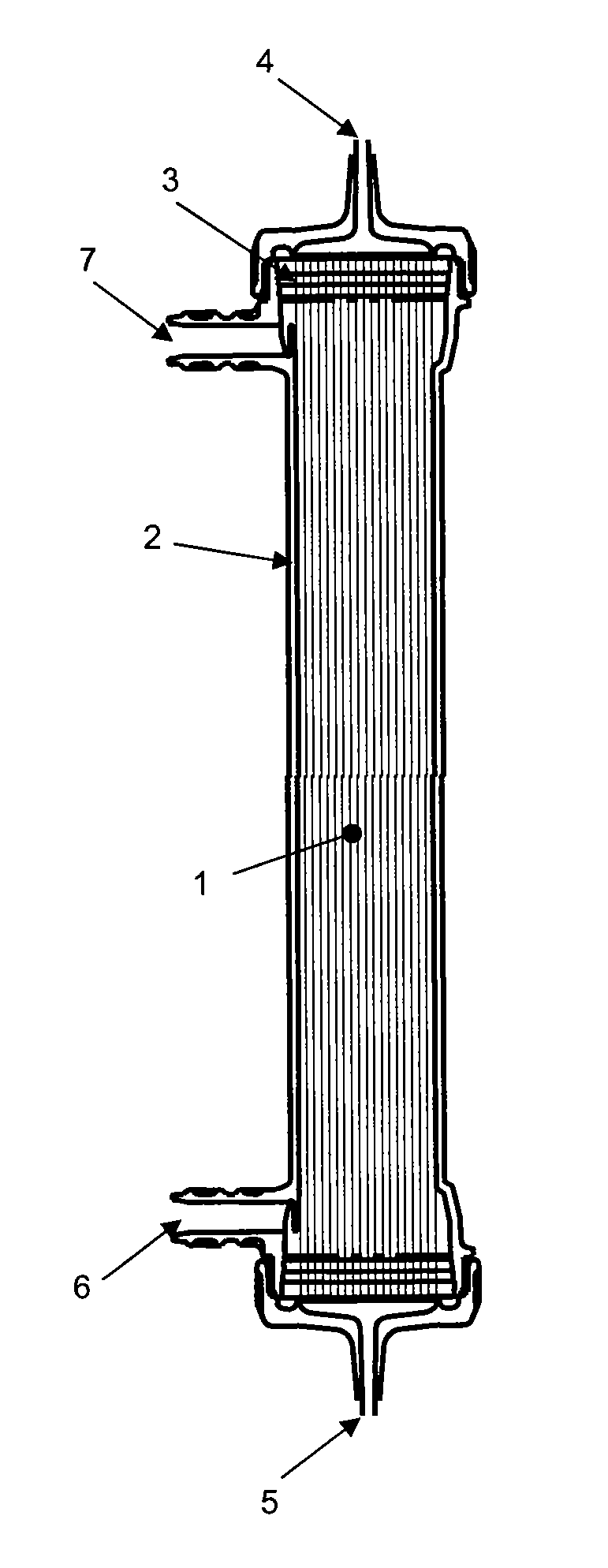
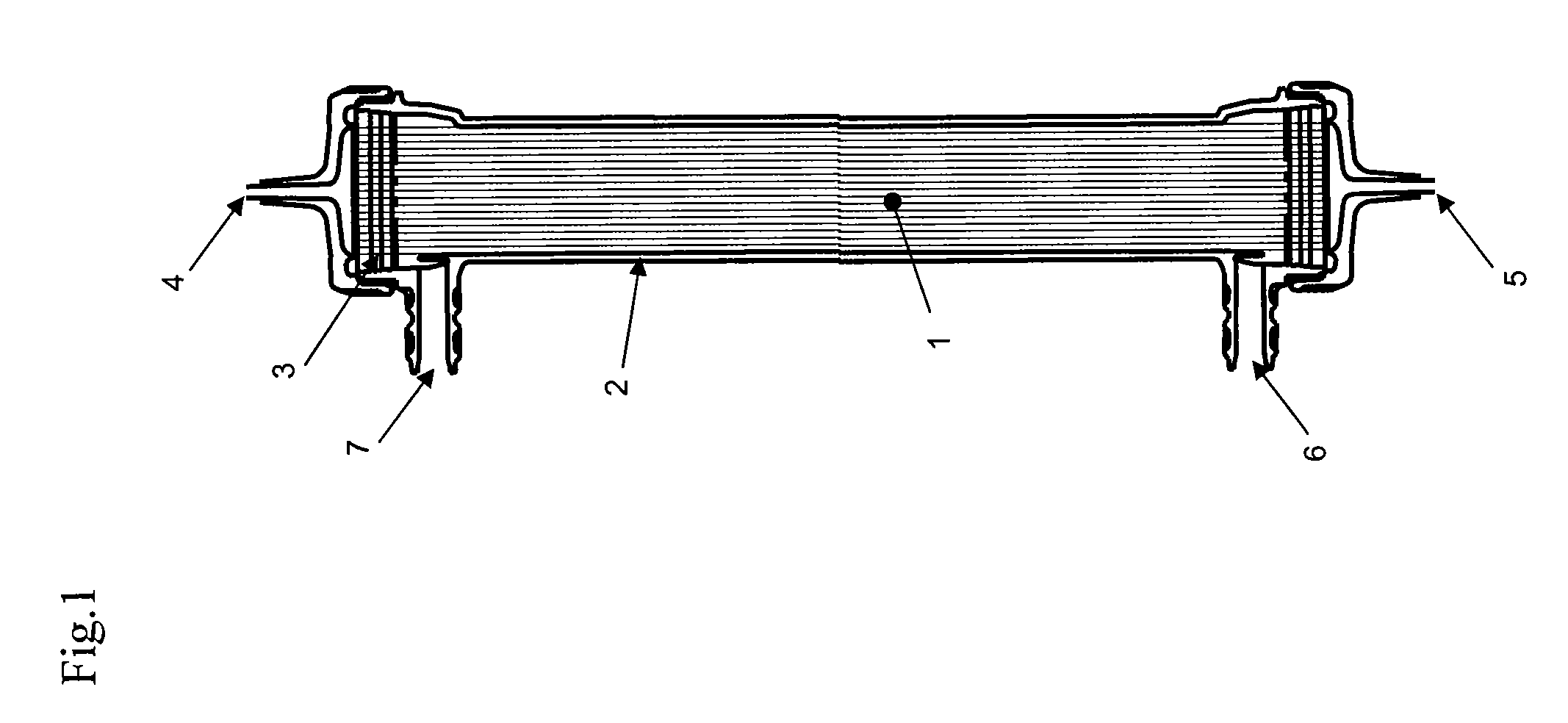
[0155]Five hundred mL of an aqueous solution of 0.1% by weight of a vinylpyrrolidone / vinyl acetate (6 / 4) copolymer (Kollidon VA64 manufactured by BASF) was allowed to pass through the hollow fiber membrane module prepared as described above from the blood side inlet (Bi) to the blood side outlet (Bo). Then, 500 mL of the solution was allowed to pass from the blood side inlet (Bi) to the dialyzate side inlet (Di), so that VA64 was accumulated on the inner surface of the hollow fiber membrane. In this process, the liquid temperature was 30° C., and the flow rate was 500 mL / minute. The VA64 placed in the hollow fiber membrane was further accumulated on the inner surface by pressing the filling liquid from the dialyzate side to the blood side with compressed air at 100 kPa. Thereafter, the filling liquid on the blood side was blown so that the aqueous solution was held only in the hollow fiber membrane. In addition, nitrogen was blown for 1 minute into each of the dialyzate side and the...

example 2

[0156]The same process as in Example 1 was performed, except that an aqueous solution of 0.01% by weight of a vinylpyrrolidone / vinyl acetate (6 / 4) copolymer (Kollidon VA64 manufactured by BASF) was used instead. The measurement of the ester carbon content was performed twice under the same conditions. The results are shown in the table below. A large amount of VA64 was successfully and uniformly localized at the surface of the functional layer, and high resistance to the deposition of platelets and high β2-microglobulin clearance performance were obtained. The β2-microglobulin clearance performance was higher in this example than in Comparative Example 1. This may be because the functional layer surface is covered with VA64 in such a degree that the effect of inhibiting the deposition of proteins and so on is higher than the effect of reducing the pore size, so that the performance is less reduced by clogging of the membrane with proteins. The water content of the insoluble componen...

example 3

[0157]The same process as in Example 1 was performed, except that an aqueous solution of 0.001% by weight of a vinylpyrrolidone / vinyl acetate (6 / 4) copolymer (Kollidon VA64 manufactured by BASF) was used instead. The measurement of the ester carbon content was performed twice under the same conditions. The results are shown in the table below. A large amount of VA64 was successfully localized at the surface of the functional layer, and high resistance to the deposition of platelets and high β2-microglobulin clearance performance were obtained. The resistance to the deposition of platelets was slightly lower in this example than in Example 1 or 2. This may be because the ester group content of the functional layer surface is lower in this example than in Example 1 or 2, so that the ester group distribution is uneven.


PUM

PropertyMeasurementUnit
angleaaaaaaaaaa
depthaaaaaaaaaa
RHaaaaaaaaaa

Abstract

A separation membrane includes a membrane comprising a polymer, characterized in that a functional layer is formed on the surface in one side of the membrane, the peak area percentage of carbon derived from ester group measured by the electron spectroscopy for chemical analysis (ESCA) on the surface of the preceding functional layer is 0.1% (by atomic number) or more but not more than 10 (% by atomic number), and the peak area percentage of carbon derived from ester group measured by the electron spectroscopy for chemical analysis (ESCA) on the surface opposite to the functional layer is not more than 10 (% by atomic number). A separation membrane module suffering from little sticking of organic matters, proteins, platelets and so on is provided with the separation membrane as a built-in membrane.

Description

CROSS-REFERENCE TO RELATED APPLICATIONS[0001]This application is the U.S. National Phase application of PCT International Application No. PCT / JP2009 / 056448, filed Mar. 30, 2009, and claims priority of Japanese Patent Application Nos. 2008-089943, filed Mar. 31, 2008, and 2008-089944, filed Mar. 31, 2008, the disclosures of which applications are incorporated herein by reference in their entirety for all purposes.FIELD OF THE INVENTION[0002]The invention relates to a separation membrane and a separation membrane module, which have high separation performance and are suitable for use in applications where compatibility with blood and resistance to the deposition of proteins or organic substances are required. For example, separation membranes for use in blood purification are required to have compatibility with blood and resistance to the deposition of proteins, and water purifier membranes, water purification membranes, waste water clarification membranes, reverse osmosis membranes, ...

Claims


Application Information

Patent Timeline
Patent Type & Authority Patents(United States)
IPC IPC(8): B01D39/00B01D63/00B01D67/00B01D11/00
CPCB01D63/02B01D69/02B01D69/08B01D71/48B01D71/40B01D71/44B01D71/68B01D71/38A61M1/16B01D2325/38B01D67/0093B01D69/087B01D2323/02B01D2323/385B01D2325/36B01D2323/2187B01D67/00416B01D71/383B01D71/4011A61M1/34
Inventor UENO, YOSHIYUKIFUJITA, MASAKISUGAYA, HIROYUKI
Owner TORAY IND INC
Learn More