Magnetic resonance system and method employing a digital SQUID

a magnetic resonance and digital squid technology, applied in the field of magnetic resonance system and digital squid, can solve the problems of large system, slow to achieve high resolution imaging over a substantial volume of tissue, inconvenient patient imaging time of many minutes,

Active Publication Date: 2013-12-31
THE JOHNSON REVOCABLE TRUST DATED 6 25 2003
View PDF8 Cites 35 Cited by
  • Summary
  • Abstract
  • Description
  • Claims
  • Application Information

AI Technical Summary

Benefits of technology

[0095]In one embodiment, this receiver can receive a wideband signal that comprises a plurality of narrowband signals such as are conventionally received in known MRI systems. These narrowband signals may be received from a plurality of input antennas, wherein the signals may be subject to analog combination before digitization. Alternatively, digital signals from a plurality of antennas may be digitally multiplexed after direct digitization. This system and method enables several techniques that lead to faster imaging with improved spatial resolution.
[0105]According to a second embodiment, shown in FIG. 2, an external multiplexer controller is used to select the signal from each pickup coil in sequence, with digital processing applied only to the selected signal. This has an advantage in reducing the required digital hardware. More generally, one may design a multiplexed system to reduce the N digital processing chains to any number between 1 and N, depending on an appropriate compromise of system complexity and performance.
[0109]While some parts of the measurement procedure of applied field gradients and pulse excitations will be similar to those in conventional MRI, spatial information in one direction (for the linear array) or in two dimensions (for the area array) will be obtained by digital analysis of the signals from the respective receiver elements, rather than by repeated application of magnetic field gradients. This will dramatically enhance the speed of the image acquisition.
[0112]In general, stronger magnetic fields will yield stronger RF signals and better imaging resolution. However, the digital SQUID detectors should permit a favorable tradeoff between high resolution and avoidance of the largest field magnitudes.
[0114]One aspect of the present system is that, in addition to magnetic field encoding of space, the use of a plurality of sensors allows direct spatial encoding of emissions; that is, n emissions aliased at the same frequency can be distinguished by using n sensors, and generally if multiple excitations are conducted with different probe patterns, further ambiguity may be resolved, and noise reduced. Thus, a single excitation pulse can be used to acquire image data from a volume, and repeated excitation used to increase resolution and reduce noise. See also, D. K. Sodickson and W. J. Manning, “Simultaneous Acquisition of Spatial Harmonics (SMASH): Fast Imaging with Radiofrequency Coil Arrays”, Magnetic Resonance in Medicine, vol. 38, pp. 591-603, 1997; K. P. Pruessman, M. Weiger, M. B. Scheidegger, and P. Boesiger, “SENSE: Sensitivity Encoding for Fast MRI”, Magnetic Resonance in Medicine, vol. 42, pp. 952-962, 1999; W. E. Kyriakos, L. P. Panych, S. F. Kacher, C.-F.Westin, S. M. Bao, R. V. Mulkern, and F. A. Jolesz, “Sensitivity Profiles from an Array of Coils for Encoding and Reconstruction in Parallel (SPACERIP)”, Magnetic Resonance in Medicine, vol. 44, pp. 301-308, 2000; Djaudat Idiyatullin, Curt Corum, Jang-Yeon Park, Michael Garwood, “Fast and quiet MRI using a swept radiofrequency”, Journal of Magnetic Resonance 181 (2006) 342-349; Wright, S.M. McDougall, M.P. Ke Feng Hollingsworth, N.A. Bosshard, J.C. Chieh-Wei Chang, “Highly Parallel Transmit / Receive Systems for Dynamic MRI”, 31st Annual International Conference of the IEEE EMBS, Minneapolis, Minn., USA, Sep. 2-6, 2009, William Scott Hoge, “An Adaptive Signal Processing Approach to Dynamic Magnetic Resonance Imaging”, Ph.D. Dissertation, Northeastern University (2001), each of which is expressly incorporated herein by reference.
[0117]A still further aspect of the technology provides an adaptive imaging technique in which an initial estimate of the image is constructed, which for example may be based on a model of the object to be imaged and prior data obtained during the same session. The model may be derived from extrinsic data sources, such as a description of the anatomy, video observation, X-ray, ultrasound, or other data. As the model is conformed to the MRI data being obtained, ambiguities may be tested by specially designed excitation to distinguish between multiple possible states. Such a model may also be dynamic, and therefore may be synchronized to respiration, cardiac cycles, neuromuscular activity, and the like. Thus, a movement of a patient need not lead to artifacts, if the degrees of freedom of the patient are understood and accounted for. This adaptive system generally requires real-time processing of the data, but using superconducting digital processors, fast traditional semiconductor processors, parallel processing computational arrays, such as graphics processor units (GPUs), such processing can be completed between each excitation cycle, allowing the image to be resolved in real time.

Problems solved by technology

A uniform, low-noise magnetic field of this magnitude requires a superconducting magnet, which yields a large and bulky system.
One disadvantage of this conventional method is that it can be quite slow to achieve high resolution imaging over a substantial volume of tissue.
An imaging time of many minutes can be inconvenient for the patient, as well as being inconsistent with moving tissues such as the heart and lungs.
While this does increase the image acquisition speed, this approach has not yet been adopted for commercial MRI systems, due in part to the complex network of RF receivers required.
A system of this type does not address the imaging speed issue (which may even be slower due to additional required signal averaging), but such a system would be substantially more compact and portable due to the small magnetic field, and therefore likely small magnet.
Still, work to date has demonstrated only a fairly low-resolution system, which would limit its applicability.
However, this partially parallel approach did not address how this small array (with 7 elements) could be scaled to much larger numbers to achieve large scan-time acceleration factors.
However, it is less well known that the SQUID itself is actually a high-frequency device, capable of field measurement up to GHz frequencies.
The frequency limitation in conventional SQUID systems is actually in the external control loop that extends the dynamic range and linearity of the device as an analog sensor of magnetic field strength and / or gradient.
In an idealized nuclear magnetic resonance experiment, the FID decays approximately exponentially with a time constant T2, but in practical MRI small differences in the static magnetic field at different spatial locations (“inhomogeneities”) cause the Larmor frequency to vary across the body creating destructive interference which shortens the FID.
In some situations it is not possible to generate enough image contrast to adequately show the anatomy or pathology of interest by adjusting the imaging parameters alone, in which case a contrast agent may be administered.
The magnet is a large and expensive component of an MRI scanner.
A permanent magnet that is powerful enough to be used in a traditional type of MRI will be extremely large and bulky; they can weigh over 100 tons.
Permanent magnet MRIs are very inexpensive to maintain; this cannot be said of the other types of MRI magnets, but there are significant drawbacks to using permanent magnets.
They are only capable of achieving weak field strengths compared to other MRI magnets (usually less than 0.4 T) and they are of limited precision and stability.
Permanent magnets also present special safety issues; since their magnetic fields cannot be “turned off,” ferromagnetic objects are virtually impossible to remove from them once they come into direct contact.
An advantage is low initial cost, but field strength and stability are limited.
The electromagnet requires considerable electrical energy during operation which can make it expensive to operate.
This design is considered obsolete for typical application.
The construction of such magnets is costly, and the cryogenic helium imposes operating costs and requires careful handling.
However, higher field strengths require more costly magnets with higher maintenance costs, and have increased safety concerns.
However, gradient performance may also be limited by safety concerns over possible nerve stimulation.
However, the increased acceleration also reduces the signal-to-noise ratio and can create residual artifacts in the image reconstruction.
The low strength of the Earth's field results in poor signal to noise ratios, requiring long scan times to capture spectroscopic data or build up MRI images.

Method used


Image

  • Magnetic resonance system and method employing a digital SQUID
  • Magnetic resonance system and method employing a digital SQUID
  • Magnetic resonance system and method employing a digital SQUID

Examples


Embodiment Construction

[0141]In a conventional MRI system of the prior art, DC magnetic gradient coils produce a magnetic field gradient that is scanned across the object to be imaged. At a given time, only a single volume slice is in resonance with the RF source (and thus excited), and only a single line in K-space is accessed, and the image is developed sequentially. This scanned, sequential nature is what makes the imaging so slow.

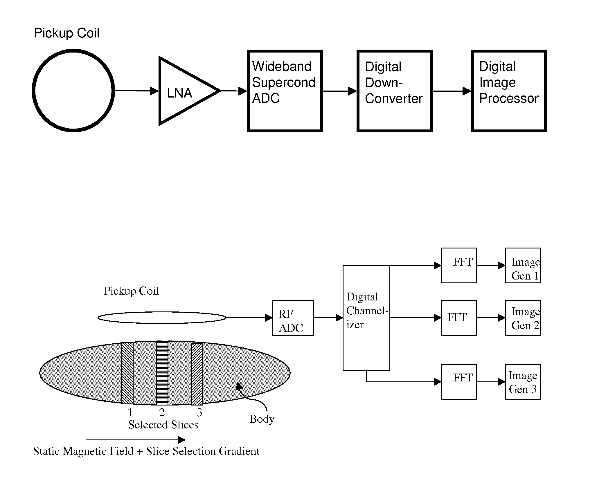
[0142]In a preferred embodiment of the MRI system, as shown in FIG. 4, each element of the detector array comprises a magnetic pickup coil or antenna, which is designed to selectively detect local electromagnetic fields surrounding the pickup coil, and generally emitted close to the pickup coil. The entire area may be in resonance, so that scanning of a gradient field across this area is not necessary, and each pixel is derived from a given antenna element. The parallel processing of the data from each antenna is what makes the imaging much faster, with a total imaging time t...


PUM


Abstract

A magnetic resonance system, comprising at least one SQUID, configured to receive a radio frequency electromagnetic signal, in a circuit configured to produce a pulsatile output having a minimum pulse frequency of at least 1 GHz which is analyzed in a processor with respect to a timebase, to generate a digital signal representing magnetic resonance information. The processor may comprise at least one rapid single flux quantum circuit. The magnetic resonance information may be image information. A plurality of SQUIDs may be provided, fed by a plurality of antennas in a spatial array, to provide parallel data acquisition. A broadband excitation may be provided to address a range of voxels per excitation cycle. The processor may digitally compensate for magnetic field inhomogeneities.

Description

CROSS REFERENCE TO RELATED APPLICATIONS[0001]This application is a Continuation of Ser. No. 12 / 954,291, filed Nov. 24, 2010, which claims benefit of priority from U.S. Provisional Patent Application Ser. No. 61 / 264,032, filed Nov. 24, 2009, the entirety of which are expressly incorporated herein by reference.BACKGROUND OF THE INVENTION[0002]Magnetic resonance imaging (MRI) is an established technology for high resolution three-dimensional imaging of the living human body, without the need for potentially hazardous x-rays. See, Joseph P. Hornak, Ph.D., The Basics of MRI, www.cis.rit.edu / htbooks / mri / (copyright 1996-2010), expressly incorporated herein by reference. This is based on magnetic resonance of the magnetic moments of hydrogen nuclei (protons) in the presence of a magnetic field. The process involves resonant absorption and emission of a radio-frequency (RF) signal in the tissue, at a frequency given by f=γB, where B is the field in teslas (T) and γ=43 MHz / T for the proton. S...

Claims


Application Information

Patent Timeline
Patent Type & Authority Patents(United States)
IPC IPC(8): G01R33/20G01V3/00
CPCG01R33/20G01R33/323G01R33/445G01V3/00G01R33/326G01R33/3621G01R33/50G01R33/567
Inventor RADPARVAR, MASOUDKADIN, ALAN M.TRACK, ELIE K.HITT, JR., RICHARD E.
Owner THE JOHNSON REVOCABLE TRUST DATED 6 25 2003
Why Eureka
Try Eureka