Air pollution control system and air pollution control method, spray drying device of dewatering filtration fluid from desulfurization discharged water, and method thereof

a technology of desulfurization and air pollution control, which is applied in the direction of liquid degasification, lighting and heating apparatus, and separation processes, etc., can solve the problems of complex desulfurization discharged water and high treatment cost, and achieve stable atomization, reduce the effect of the deposi

Active Publication Date: 2014-05-06
MITSUBISHI POWER LTD
View PDF20 Cites 14 Cited by
  • Summary
  • Abstract
  • Description
  • Claims
  • Application Information

AI Technical Summary

Benefits of technology

[0039]According to the air pollution control system and the air pollution control method of the present invention, the dewatering filtration fluid acquired by removing gypsum from the desulfurization discharged water separated from the desulfurizer is atomized by the spray drying device, by using flue gas from the boiler. Therefore, spray drying can be stably performed, thereby enabling to realize zero liquid discharge of the desulfurization discharged water from the desulfurizer.
[0040]According to the present invention, further, at the time of atomization by the spray drying device by using the desulfurization discharged water acquired by removing gypsum from the desulfurization discharged water separated from the desulfurizer, stable atomization can be performed while ascertaining a spray-dried state, and reducing the deposit when there is insufficient atomization. Accordingly, zero liquid discharge of the desulfurization discharged water from the desulfurizer can be realized.

Problems solved by technology

However, a removing process of these various types of harmful substances contained in the desulfurization discharged water is complicated, and treatment cost is high.

Method used


Image

  • Air pollution control system and air pollution control method, spray drying device of dewatering filtration fluid from desulfurization discharged water, and method thereof
  • Air pollution control system and air pollution control method, spray drying device of dewatering filtration fluid from desulfurization discharged water, and method thereof
  • Air pollution control system and air pollution control method, spray drying device of dewatering filtration fluid from desulfurization discharged water, and method thereof

Examples


first embodiment

[First Embodiment]

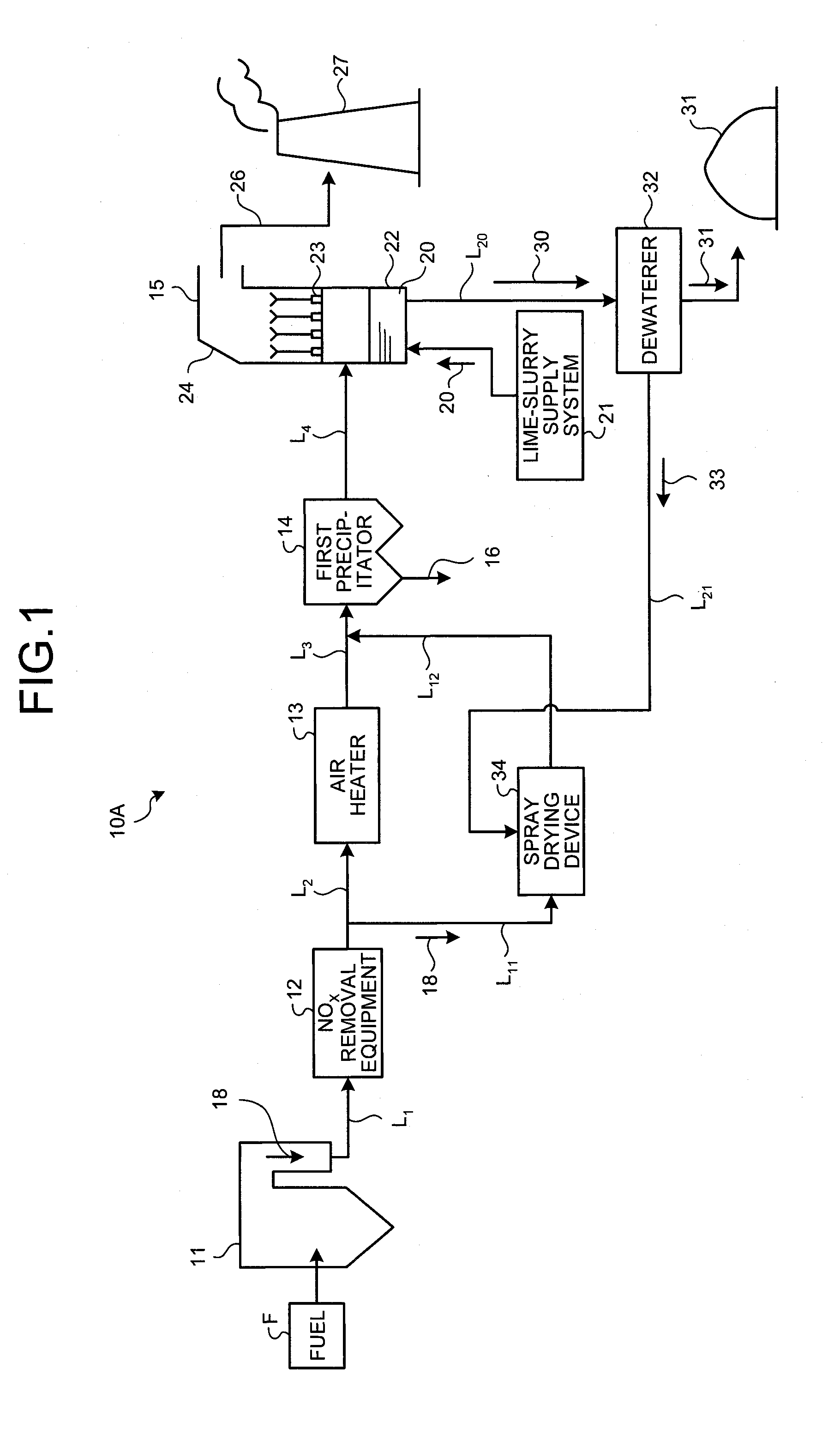
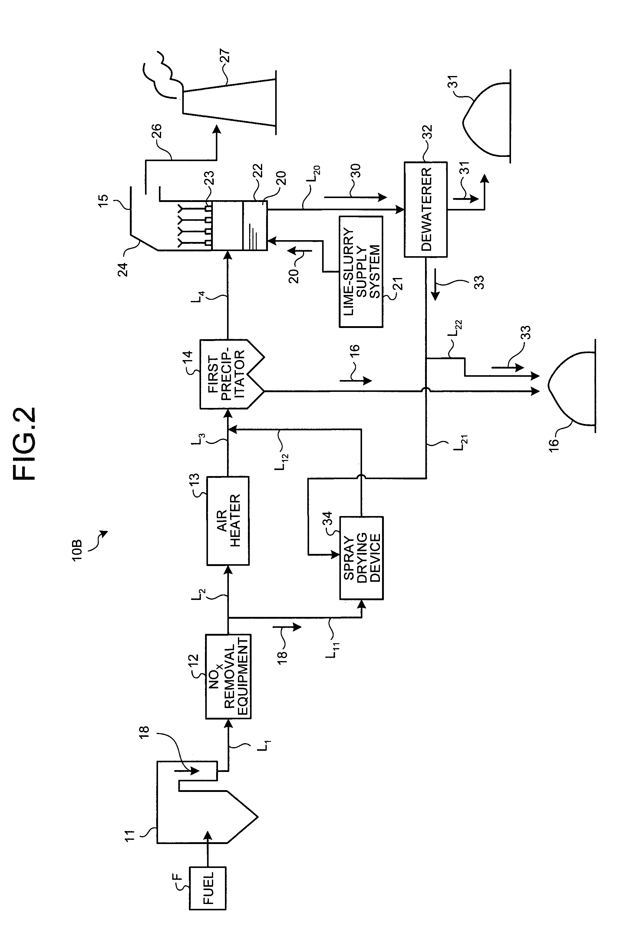
[0070]FIG. 1 is a schematic configuration diagram of an air pollution control system according to a first embodiment of the present invention. An air pollution control system 10A exemplified in FIG. 1 removes harmful substances such as nitrogen oxides (NOx), sulfur oxides (SOX), and mercury (Hg) from flue gas 18 discharged from a boiler 11 such as a coal combustion boiler that uses coals as a fuel or a heavy-oil combustion boiler that uses heavy oil as a fuel.

[0071]The air pollution control system 10A includes the boiler 11 that combusts fuel F, an air heater 13 that recovers heat of the flue gas 18 from the boiler 11, a first precipitator 14 that reduces dust in the flue gas 18 after heat recovery, a desulfurizer 15 that reduces sulfur oxides in the flue gas 18 after dust reduction by a lime slurry 20, which is an absorbent, a dewaterer 32 that reduces gypsum 31 from desulfurization discharged water 30 discharged from the desulfurizer 15, a spray drying device 34 ...

second embodiment

[Second Embodiment]

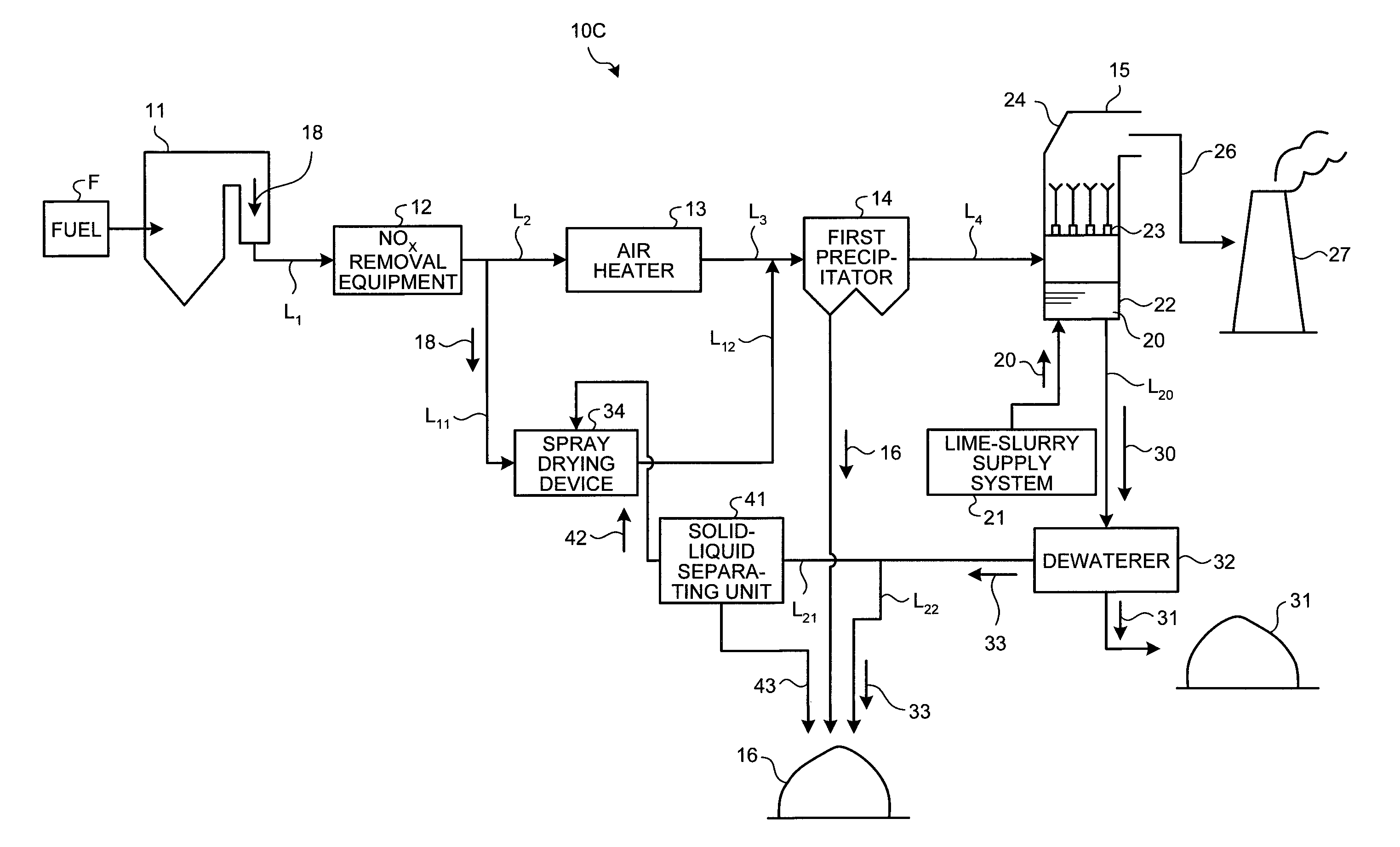
[0093]An air pollution control system according to a second embodiment of the present invention is explained next. Constituent elements identical to those in the first embodiment described above are denoted by like reference signs, and explanations thereof will be omitted. FIG. 3 is a schematic configuration diagram of the air pollution control system according to the second embodiment. In an air pollution control system 10C according to the second embodiment, as shown in FIG. 3, a solid-liquid separating unit 41 that reduces suspended solids (SS) or suspended substance in the dewatering filtration fluid 33 is installed in the dewatering line L21.

[0094]As the solid-liquid separating unit 41, for example, a hydraulic cyclone, a belt filter, a classifier, or a membrane separator can be mentioned.

[0095]The solid-liquid separating unit 41 reduces suspended solids (SS) in the dewatering filtration fluid 33 so that an SS concentration in a separate liquid 42 becomes equ...

third embodiment

[Third Embodiment]

[0100]An air pollution control system according to a third embodiment of the present invention is explained next. Constituent elements identical to those in the first embodiment described above are denoted by like reference signs, and explanations thereof will be omitted. FIG. 4A is a schematic configuration diagram of the air pollution control system according to the third embodiment. FIG. 4B is a schematic configuration diagram of another air pollution control system according to the third embodiment. FIG. 4C is a schematic configuration diagram of still another air pollution control system according to the third embodiment. In an air pollution control system 10D-1 according to the third embodiment, as shown in FIG. 4A, a small second precipitator 35 is provided on the downstream side of the spray drying device 34 to reduce solid matters.

[0101]As the small second precipitator 35, for example, a bag filter or an electric dust collector can be used. Accordingly, a ...


PUM

PropertyMeasurementUnit
temperatureaaaaaaaaaa

Abstract

To include a boiler 11 that burns fuel F, an air heater 13 that recovers heat of flue gas 18 from the boiler 11, a first precipitator 14 that reduces dust in the flue gas 18 after heat recovery, a desulfurizer 15 that reduces sulfur oxides in the flue gas 18 after dust reduction by an absorbent, a dewaterer 32 that reduces gypsum 31 from desulfurization discharged water 30 discharged from the desulfurizer 15, a spray drying device 34 including an atomizer that atomizes a dewatering filtration fluid 33 discharged from the dewaterer 32, and a flue-gas introducing line L11 that introduces a part of the flue gas 18 into the spray drying device 34.

Description

TECHNICAL FIELD[0001]The present invention relates to an air pollution control system that treats flue gas discharged from a boiler, an air pollution control method, a spray drying device of a dewatering filtration fluid from desulfurization discharged water, and a method thereof.BACKGROUND ART[0002]Conventionally, there has been known an air pollution control system for treating flue gas discharged from a boiler installed in a thermal power generation plant or the like. The air pollution control system includes NOx removal equipment that removes nitrogen oxides from flue gas discharged from a boiler, an air heater that recovers heat of flue gas having passed through the NOx removal equipment, a precipitator that reduces dust in the flue gas after heat recovery, and a desulfurizer that reduces sulfur oxides in the flue gas after dust reduction. As the desulfurizer, a wet desulfurizer that reduces sulfur oxides in flue gas by bringing a lime absorbent into gas-liquid contact with flu...

Claims


Application Information

Patent Timeline
Patent Type & Authority Patents(United States)
IPC IPC(8): B01D53/14B01D47/00
CPCB01D53/96B01D53/50B01D2251/404B01D1/18B01D53/501B01D53/505F23J15/04B01D1/14B01D1/20F23J15/022B01D53/1425Y02P70/10B01D53/14B01D53/78B01D53/1481B01D53/80B01D53/8625B01D2257/302B01D2257/602C02F1/048C02F1/12C02F1/281C02F1/441C02F1/4693C02F1/52C02F2001/5218C02F2101/101C02F2101/106C02F2101/108C02F2101/12C02F2101/20C02F2103/18F23J15/00F23J15/003
Inventor UKAI, NOBUYUKIKAGAWA, SEIJINAGAYASU, TATSUTOKAMIYAMA, NAOYUKIFUKUDA, TOSHIHIRO
Owner MITSUBISHI POWER LTD
Why Eureka
Try Eureka