Although the applied electric
trapping field helps keeping the ions from escaping the
cell, it deteriorates the conditions for a clean measurement of the cyclotron frequency.
A resistive detection circuit can also induce an increase in magnetron radii due to loss of the
potential energy by image current damping.
A deviation of individual
electrode shapes from the calculated ideal shapes or a deviation of the assembled cell from its ideal shape can cause
asymmetry of the
electric field inside the cell.
Although these shapes are mostly straightforward, deviations from perfect shapes can still occur if the tolerances are not correctly defined, if the individual electrodes are not
cut out of one and the same cylindrical
raw material, or if the
assembly of the cell is not perfect.
In the FT-ICR cells of more complex nature this remains a challenge.
There is a non-zero probability that some individual electrodes of a multitude of mantle electrodes of an ICR cell may deviate to a different extent from the corresponding ideal shape and / or alignment so that the ensuing perturbation of the desired ideal
electric field axis may also be non-uniform, for instance, in that a radial shift of the electric field center varies along the longitudinal extension of the cell.
If the tolerances of the electrodes are not correctly kept, or if the final
assembly of so many electrodes is not perfectly performed these cells are also susceptible to generate electric field errors inside.
In more complicated cases, however, these field errors may also lead to at least one of a tilting (e.g., the electric field axis and geometric axis of the ICR cell are not parallel any more), a bending (e.g., the electric field axis is not a straight line any more, but a non-linear 2D or 3D curve), and a rippling (e.g., the electric axis comprises a stepped pattern with abrupt shifts where a perturbation changes significantly) of the electric field axis (e.g., non-uniform perturbation).
The inverse-leaf electrodes (e.g., 57, 59, 66, 68) are normally not used as detection electrodes since these are connected to
DC voltage power supplies and thus lead to noisy ICR signals.
Another cause of symmetry errors of the electric field inside the ICR cell may originate from the contact potentials of connectors from the power supply.
Depending on the location of these contact potential effects this problem can cause asymmetric electric field inside the cell.
However, if they are connected to the ground over a large
resistor, which picks up the extremely low induced image charge
signal, this can make it difficult to have a quick and easy
discharge after every acquisition cycle.
This usually happens if the metallic surface of the
electrode carries a
dielectric layer, which (a) can be polarized or charged and (b) cannot easily be discharged due to its lack of conductance.
An uneven distribution of surface
contamination on individual longitudinal electrodes can lead to asymmetric surface charging.
As a consequence, a
radial displacement of the electric field center can have different magnitudes at different points along the cell axis, which in turn leads to a non-uniform electric field perturbation within the cell.
Depending on the compounds being measured, the quench event can also produce a
dielectric layer on the inside of this
trapping plate, which can then, due to surface charging, deteriorate the
axial symmetry of the electric field.
Thus, the
layers may not get completely eliminated.
Contamination sources external to the ICR cell include the vacuum components that, for some reason, cannot be kept clean enough.
Due to this
delay, contaminants can initially thermally desorb off the
vacuum chamber walls, can condense at the
electrode surfaces of the cold ICR cell and cause surface charging.
Any
distortion /
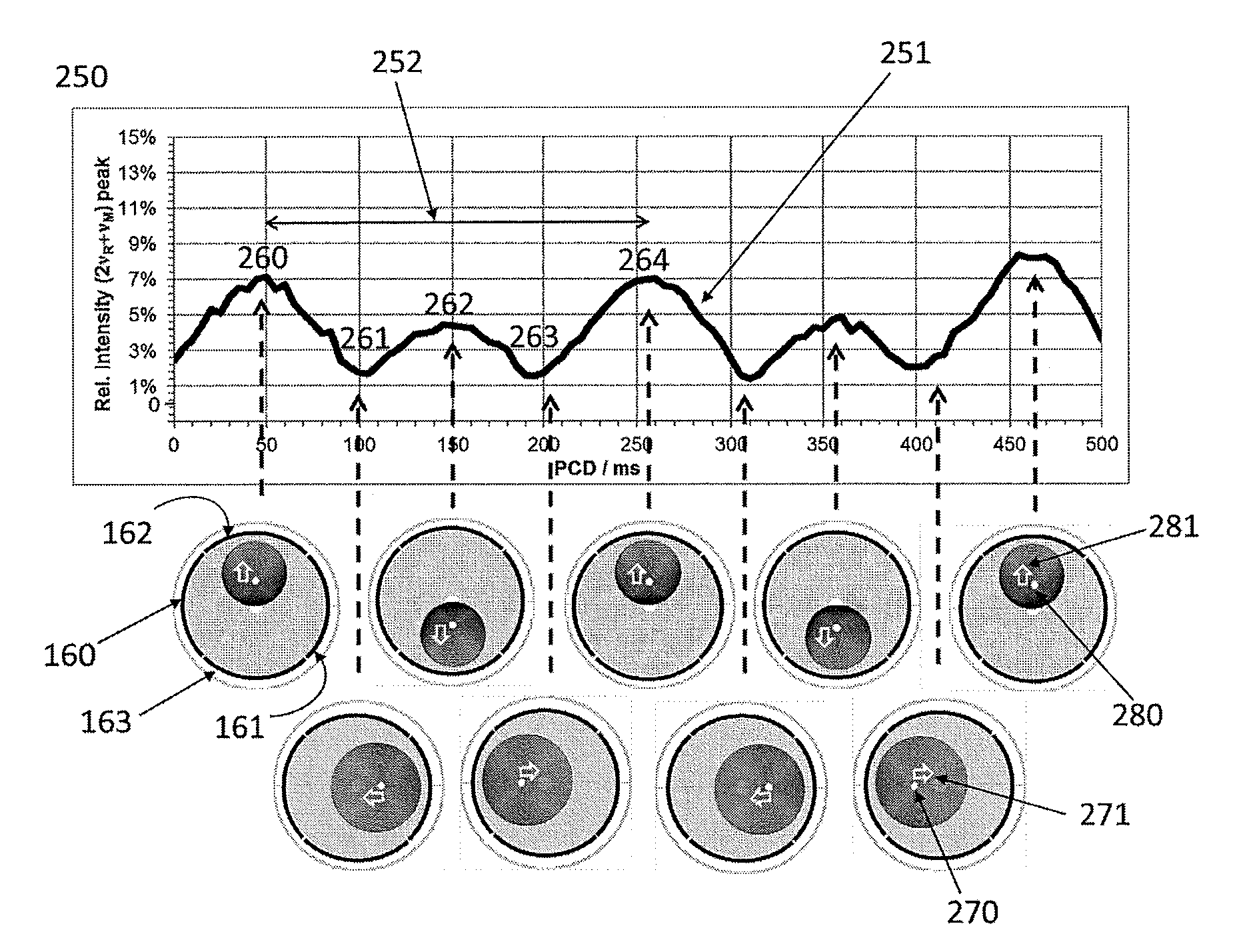
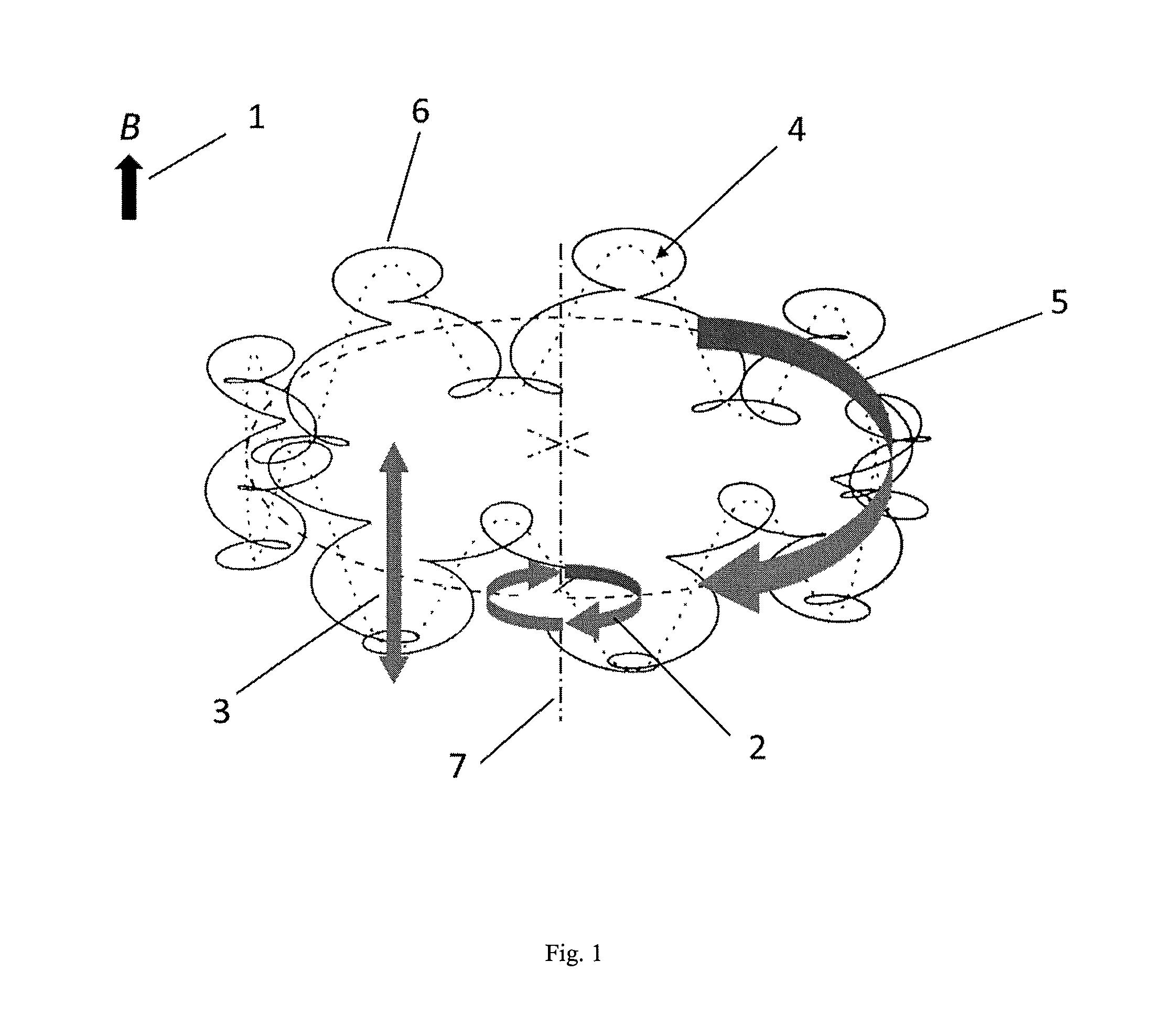
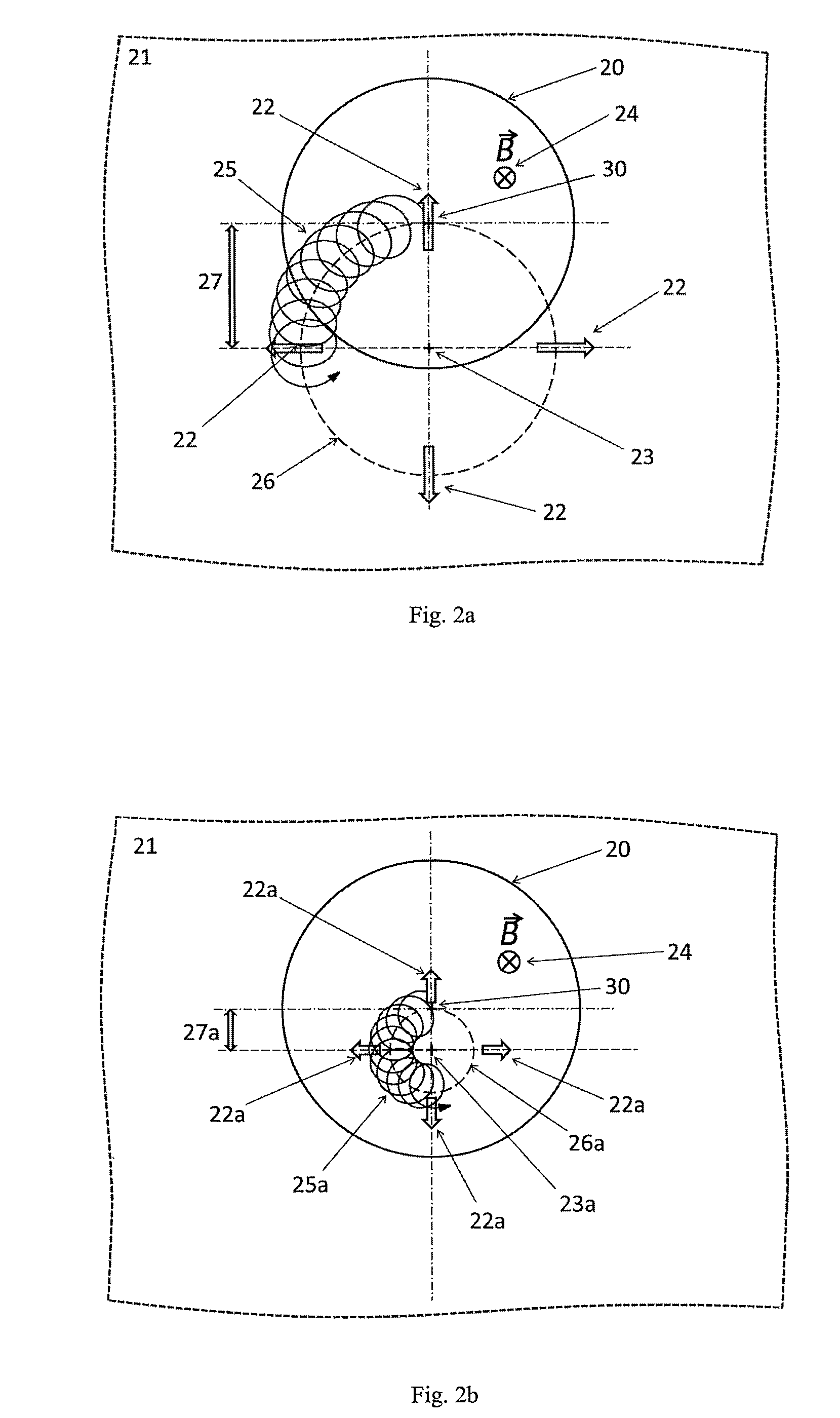
asymmetry of the electric field or improper injection of an ion packet into the ICR cell, however, entails a magnetron motion of the ions in the ICR cell.
In extreme cases, ions can be lost during the cyclotron excitation, when they are on large and offset magnetron orbits that are close to the cylinder mantle electrodes.
However, this method can only be successfully applied if ions have no magnetron orbits or if these are vanishingly small.
Moderate or large magnetron orbits severely complicate the ICR mass spectra and reduce the
signal intensity of the multiple-frequency mass peaks.
Unfortunately,
experimental methods to reduce the magnetron motion with cooling using a resonant
buffer gas are not generally applicable since they are very mass selective and require the introduction of relatively high amounts of gas into the ultrahigh
vacuum chamber.
However, these are not realistic conditions to fulfill.
However these are zones which are too close to the electrodes and have no practical importance during (most of the) regular operations of an ICR cell.
However, it is not advantageous to detect with small electrodes like 60° since the generated image current signal will be smaller than a signal detected e.g., using 90° electrodes.
As described above, the use of 120° excitation electrodes generates a homogeneous dipolar excitation field but it makes detection and correction of an offset electric
DC field in the cell difficult.
Therefore, an electric field correction by observing and minimizing the
harmonics will be difficult when using 120° electrodes for excitation and detection.
Therefore, a moderately sized, offset magnetron
orbit cannot be corrected.
A consequence of exciting and detecting with 120° segment electrodes is that the correction of a possible offset of the radial DC electric field in the ICR cell using the method according to the U.S. pending
patent application Ser. No. 13 / 767,595 will not work.


